Compression mechanism for refrigeration system

a compressor and refrigeration system technology, applied in the direction of machines/engines, positive displacement liquid engines, lighting and heating apparatus, etc., can solve the problems of difficult to supply sufficient oil to the running compressor, and the oil equalizing circuit becomes more complex

Inactive Publication Date: 2005-09-27
DAIKIN IND LTD
View PDF5 Cites 6 Cited by
  • Summary
  • Abstract
  • Description
  • Claims
  • Application Information

AI Technical Summary

Benefits of technology

[0005]The object of the present invention is to provide a compression mechanism having an oil equalizing circuit that can supply sufficient oil to the compressors that are running—even during partial load operation.
[0008]Furthermore, the oil flow of this refrigeration system compression mechanism is configured such that when the first to kth compressors are running and the k+1 to nth compressors are not running, the oil delivered from the kth oil return pipe to the intake side of the k+1 compressor is fed to the refrigerant intake main pipe and drawn together with gaseous refrigerant into the first compressor, which is connected farther downstream than the k+1 compressor. Since the kth compressor is connected to the refrigerant intake main pipe at a more upstream position than the k+1 compressor, an oil circulation cycle is achieved in which the oil returned through the kth oil return pipe is not drawn again into the second to kth compressors (i.e., running compressors other than the first compressor) but rather passes through each of the running compressors in turn in the same manner as when all of the first to nth compressors are running. As a result, oil is reliably delivered to the compressors that are running, i.e., the first to kth compressors.
[0009]Thus, with this compression mechanism, oil can be delivered reliably to the compressors that are running even when the system is operated in partial load mode.
[0013]With this refrigeration system compression mechanism, the oil is reliably drawn into the first compressor because the oil delivered to the refrigerant intake main pipe from the second to n intake branch pipes flows readily toward the part where the refrigerant intake main pipe connects to the first intake branch pipe. Thus, the reliability of the oil supply to the compressors is improved.
[0017]Moreover, the oil flow of this refrigeration system compression mechanism is configured such that when the first and second compressors are running and the third compressor is not running, the oil delivered from the second oil return pipe to the intake side of the third compressor is fed to the refrigerant intake main pipe and drawn together with gaseous refrigerant into the first compressor through the first intake branch pipe, which is connected farther downstream than the third compressor. Since the second compressor is connected to the refrigerant intake main pipe at a more upstream position than the third compressor, an oil circulation cycle is achieved in which the oil returned through the second oil return pipe is not drawn again into the second compressor but rather passes through each of the compressors in turn in the same manner as when the first, second, and third compressors are all running. As a result, oil is reliably delivered to the compressors that are running, i.e., the first and second compressors.
[0018]Thus, with this refrigeration system compression mechanism, oil can be delivered reliably to the compressors that are running even when the system is operated in partial load mode with only the first compressor running or only the first and second compressors running.

Problems solved by technology

In the conventional compression mechanism just described, the oil equalizing circuit around the compressors becomes complex because it includes a return pipe for each compressor and a plurality of equalizing pipes connected between the compressors.
The larger the number of compressors, the more complex the oil equalizing circuit becomes.
In a system whose compression mechanism has three or more compressors, a plurality of combinations of running compressors and stopped compressors occur when the system is operated in partial load mode and it is difficult to supply sufficient oil to the running compressors during all of the operating combinations.

Method used


Image

  • Compression mechanism for refrigeration system
  • Compression mechanism for refrigeration system
  • Compression mechanism for refrigeration system

Examples


first embodiment

[0025][First Embodiment]

[0026](1) Constituent Features of the Refrigeration System Compression Mechanism

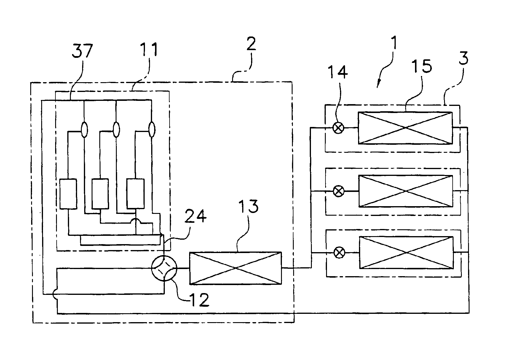
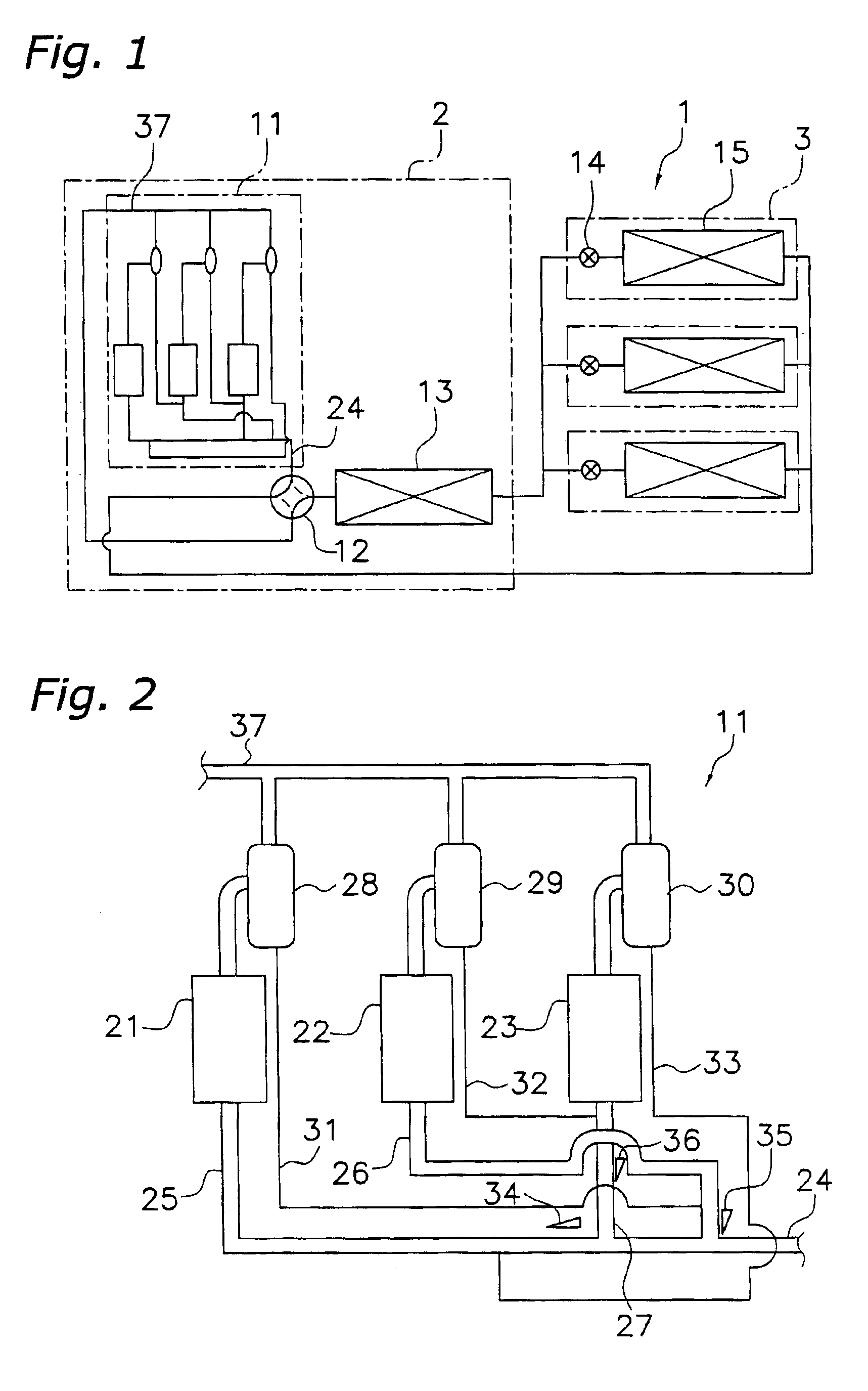
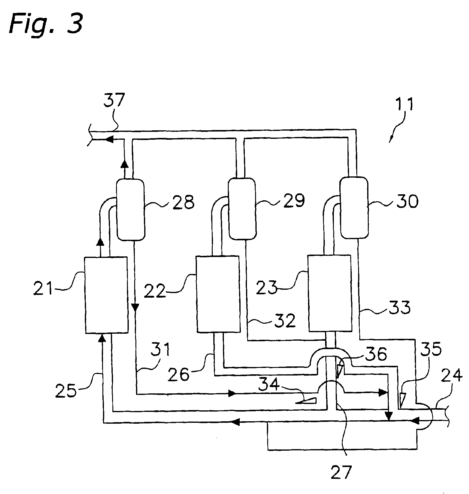
[0027]One example of a vapor compression refrigeration system provided with a compression mechanism having a plurality of compressors is a air conditioning system 1 provided with a refrigerant circuit like that shown in FIG. 1. The air conditioning system 1 is provided with one heat source unit 2 and a plurality of user units 3 connected in parallel thereto. It is used, for example, to air-condition an office building or the like. The heat source unit 2 is equipped chiefly with a compression mechanism 11, a four-way selector valve 12, and heat-source-side heat exchanger 13. In this embodiment, air or water serving as a heat source is supplied to the heat-source-side heat exchanger 13 and the heat-source-side heat exchanger 13 serves to exchange heat between the heat source and the refrigerant. The user units 3 are each equipped with an expansion valve 14 and a user side heat excha...

second embodiment

[0055][Second Embodiment]

[0056]While the first embodiment regards a compression mechanism 11 provided with three compressors, this embodiment regards a compression mechanism provided with multiple, i.e., more than three, compressors. A compression mechanisms provide with “multiple compressors” might have, for example, four or six compressors, but this embodiment describes a generalized configuration having n compressors, i.e., first to nth compressors (where n is any integer equal to or greater than 3).

[0057]FIG. 6 illustrates a compression mechanism 111 provided with n compressors, i.e., first to nth compressors. The compression mechanism 111 is provided with n (first to nth) compressors C1 to Cn, a refrigerant intake main pipe 124, n intake branch pipes L1 to Ln, n oil separators S1 to Sn, and n oil return pipes R1 to Rn. The refrigerant pipes at the outlets of the n oil separators S1 to Sn each merge with the discharge merge pipe 137. The refrigerant intake main pipe 124 and the ...


PUM


Abstract

The present invention provides an oil equalizing circuit for a refrigeration system provided with a plurality of compression mechanisms, the oil equalizing circuit being capable of supplying sufficient oil to the compressors that are running during partial load operation. The refrigeration system compression mechanism is provided with the following: first, second, and third compressors; a refrigerant intake main pipe; first, second, and third intake branch pipes connected to the intake sides of the compressors; first, second, and third oil separators connected to the discharge sides of the compressors; and first, second, and third oil return pipes provided on the oil separators. The first oil return pipe is configured such that oil is delivered to the refrigerant intake main pipe due to gravity when only the first compressor is running. The second oil return pipe is configured such that oil is delivered to the refrigerant intake main pipe due to gravity when only the first and second compressors are running.

Description

TECHNICAL FIELD[0001]The present invention relates to a compression mechanism for refrigeration systems and, more particularly, to a compression mechanism constituting a refrigerant circuit of a vapor compression refrigeration system.BACKGROUND ART[0002]One example of conventional vapor compression refrigeration systems provided with a compression mechanism having a plurality of compressors are air conditioning systems used to air-condition buildings. This kind of air conditioning system is provided with a plurality of user units and a heat source unit with a large capacity that is sufficient for accommodating the heating and cooling loads of the user units. In order to enable the system to be operated in a partial load mode, the heat source unit is provided with a compression mechanism made up of a plurality of comparatively small-capacity compressors connected in parallel. The compression mechanism is provided with an oil equalizing circuit including an oil separator connected to ...

Claims


Application Information

Patent Timeline
Patent Type & Authority Patents(United States)
IPC IPC(8): F25B1/00F04B39/02F25B13/00F25B31/00
CPCF04B39/02F25B13/00F25B31/002F25B31/004F25B2313/023F25B2400/075F25B2500/01F25B2500/27F25B43/00
Inventor MATSUOKA, HIROMUNE
Owner DAIKIN IND LTD
Why Eureka
Try Eureka