Fiber-pigtailed assembly

a fiber-pigtail and assembly technology, applied in the field of fiber-pigtail assembly, can solve the problems of difficult or impossible to find a company that can or will build such a device for the limited t&m market, and the difficulty of achieving low back reflection and low pdr simultaneously

Inactive Publication Date: 2005-09-27
TEKTRONIX INC
View PDF8 Cites 39 Cited by
  • Summary
  • Abstract
  • Description
  • Claims
  • Application Information

AI Technical Summary

Problems solved by technology

Low back reflection and low PDR tend to be difficult to achieve simultaneously.
Usually methods that improve one make the other worse.
Since T&M applications are a small percentage of the overall market for such devices, it is often difficult or impossible to find a company that can or will build such a device for the limited T&M market.
These coatings are based on interference, however, and so exhibit wavelength dependence.
Even at the optimized wavelength, coatings have difficulty achieving the best-desired specifications.
For applications involving wide-band detection, i.e., over many hundreds of nanometers of wavelength, the performance of such coatings is a serious limitation.
The resulting reflected light is thus angled such that it fails to couple to guided fiber modes and is quickly lost.
Unlike coatings, tilted surfaces are inherently broadband, resulting in very low reflectivity.
The problem is that the optimum way of achieving low back reflection, as indicated above, is to use tilted surfaces, yet tilted surfaces introduce polarization dependencies.
This problem is amplified in pigtailed optical detectors because the optical pigtail acts like a weak Fabry-Perot resonator, with a birefringent medium (the fiber itself) between mirrors (the reflective ends of the fiber pigtail).
However rotation of these terms interferes with their ability to coherently mix, resulting in modulation of the transmitted optical power, i.e., the modulation is a function of the birefringence and wavelength.

Method used


Image

  • Fiber-pigtailed assembly
  • Fiber-pigtailed assembly
  • Fiber-pigtailed assembly

Examples


Embodiment Construction

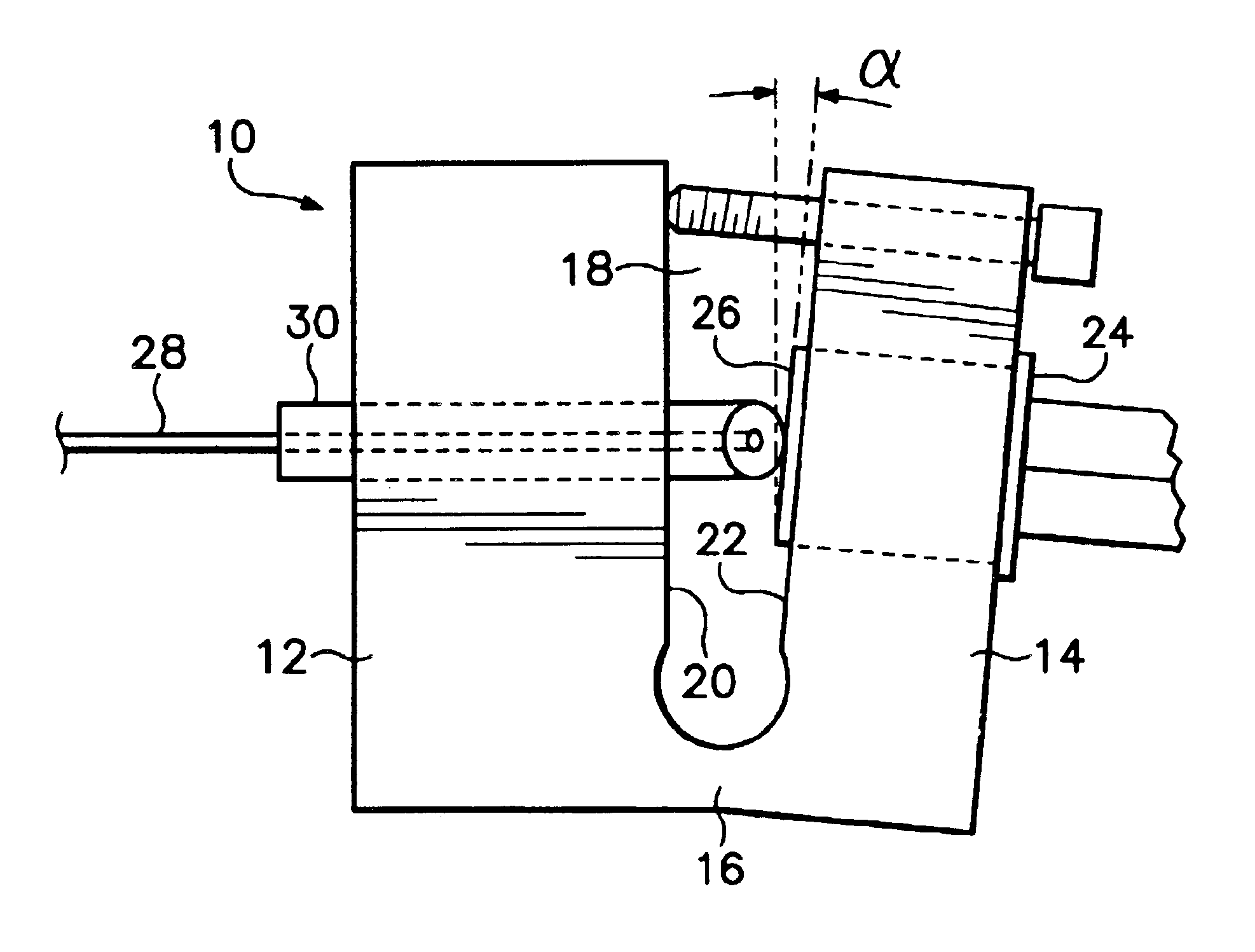
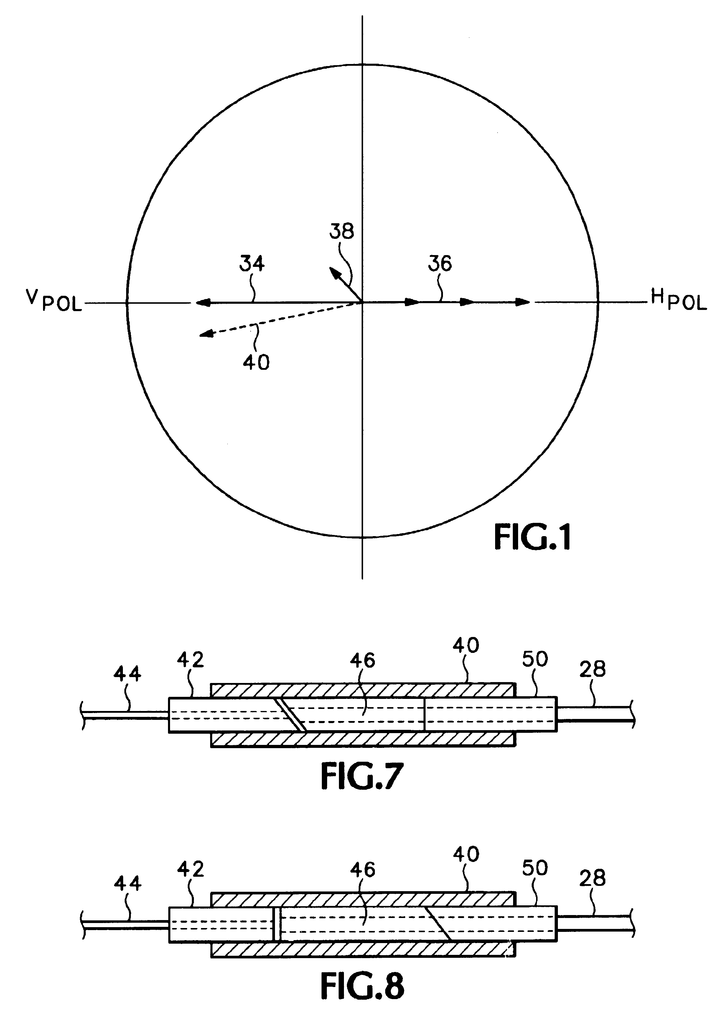
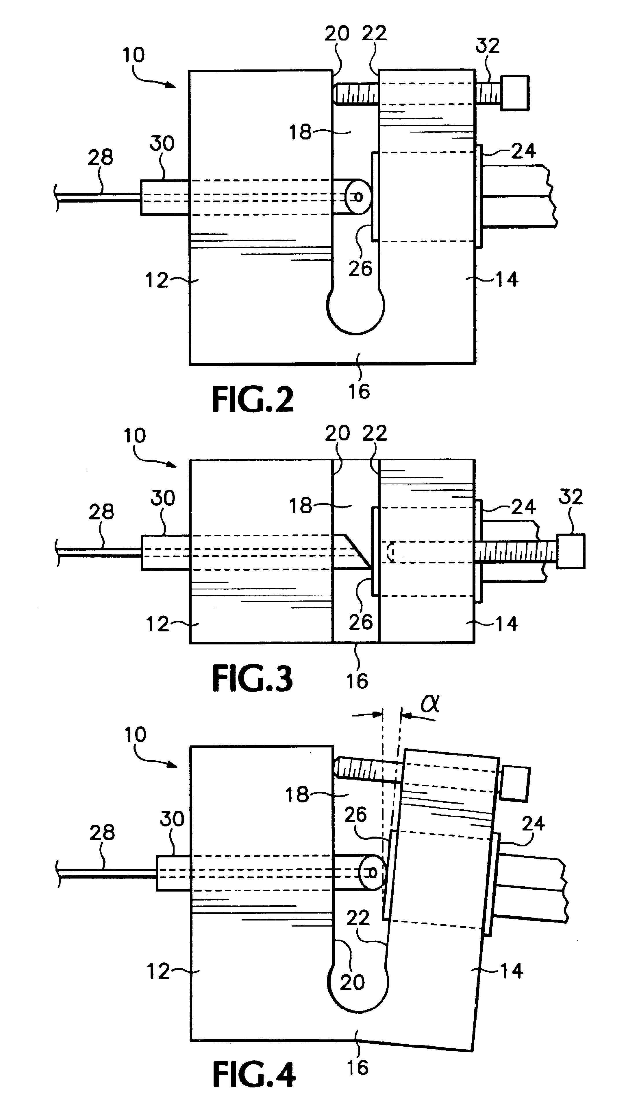
[0023]As discussed above, merely butting a flat end of a fiber pigtail to a detection surface of an optical detector results in reflection from the flat end that is fed back to an optical source, resulting in unwanted modulation of the optical source. Also the additional reflection from the other end of the fiber pigtail which is coupled to an external optical fiber sets up a birefringent cavity which is polarization dependent, i.e., introduces polarization-dependent loss (PDL) in the fiber pigtail. Therefore to reduce back reflections the end of the fiber pigtail adjacent to the detection surface is beveled. However this introduces a fixed amount of PDL into the optical detector. This may be represented as a fixed vector 34 as shown in FIG. 1. Tilting the detector surface approximately orthogonal to the plane of the bevel of the fiber pigtail introduces a variable magnitude PDL as a function of the tilt angle in the opposite direction, as shown by the variable vector 36. There may ...


PUM


Abstract

A fiber-pigtailed assembly for an optical detector with low back reflection and minimal polarization-dependent responsivity has a detector surface mounted adjacent a beveled end of a fiber pigtail such that the detector surface is tilted and rotated with respect to the beveled end of the fiber pigtail. Also an external optical fiber may be coupled to the fiber pigtail with low back reflection and minimal polarization-dependent responsivity by having an input ferrule at the end of the external optical fiber, the end being beveled; by having an intermediate ferrule at a coupling end of the fiber pigtail, the coupling end being beveled while the other end of the ferrule is beveled by the same amount but approximately orthogonal to the coupling end; and by having an output ferrule on the fiber pigtail adjacent to the intermediate ferrule, the end of the output ferrule adjacent to the intermediate ferrule being beveled. The ferrules are maintained in position so that the beveled ends of the intermediate ferrule are parallel to the corresponding beveled ends of the input and output ferrules and there is a gap between the input and intermediate ferrules. The beveled ends of the ferrules at both the coupler and detector ends of the fiber pigtail introduce fixed amounts of polarization-dependent responsivity while reducing back reflection, while the tilt of the detector surface at the detector end and the opposite approximately orthogonal bevel of the intermediate ferrule at the coupler end compensate and essentially eliminate such polarization-dependent responsivity.

Description

CROSS-REFERENCE TO RELATED APPLICATIONS[0001]This application is a divisional application of pending U.S. patent application Ser. No. 10 / 058,585 filed Jan. 24, 2002.BACKGROUND OF THE INVENTION[0002]The present invention relates to coupling light onto an optical detector, and more particularly to a fiber-pigtailed assembly that couples light from an optical fiber onto an optical detector having a relatively large area such that the polarization-dependent responsivity and back reflection are very low.[0003]Polarization-dependent responsivity (PDR) is the ratio of the maximum photo-current divided by the minimum photo-current generated in an optical detector for a given flux of photons over all possible states of polarization and correlates to polarization-dependent loss (PDL). Ideally PDR is zero dB. Reflectivity is the flux of photons that travel backward to the optical source divided by the flux of photons impinging upon the optical detector, usually expressed in dB. Ideally the ref...

Claims


Application Information

Patent Timeline
Patent Type & Authority Patents(United States)
IPC IPC(8): G02B6/42G02B6/38
CPCG02B6/4207G02B6/3822G02B6/4226
Inventor ANDERSON, DUWAYNE R.
Owner TEKTRONIX INC
Why Eureka
Try Eureka