Flow rack

a technology of flow racks and rollers, applied in the direction of hand carts, conveyor parts, transportation and packaging, etc., can solve the problems of system decommissioning, tedious replacement of single rollers, and waste of man hours for replacement, and achieve the effect of simple replacement of rollers, convenient assembly and easy maneuverability

Inactive Publication Date: 2005-09-27
LIFE TIME SYST
View PDF23 Cites 148 Cited by
  • Summary
  • Abstract
  • Description
  • Claims
  • Application Information

AI Technical Summary

Benefits of technology

[0009]The wire flow rack system of the present invention can provide a variety of benefits. First, due to the wire configuration, the rack system is easy to assemble and has only a limited number of replaceable parts, e.g., the rollers. Second, due to the wire rack configuration, the system is m

Problems solved by technology

First, because several rollers are disposed on a single shaft, the replacement of a single, worn-out or damaged roller is tedious.
This consumes man hours for the replacement, and also results in the particular rack system being decommissioned until the roller is replaced.
Second, the replacement of the rollers requires the use of one or more tools to loosen the end nuts of the roller shaft.
If a roller repairman is not equipped with the approp

Method used


Image

  • Flow rack
  • Flow rack
  • Flow rack

Examples


Embodiment Construction

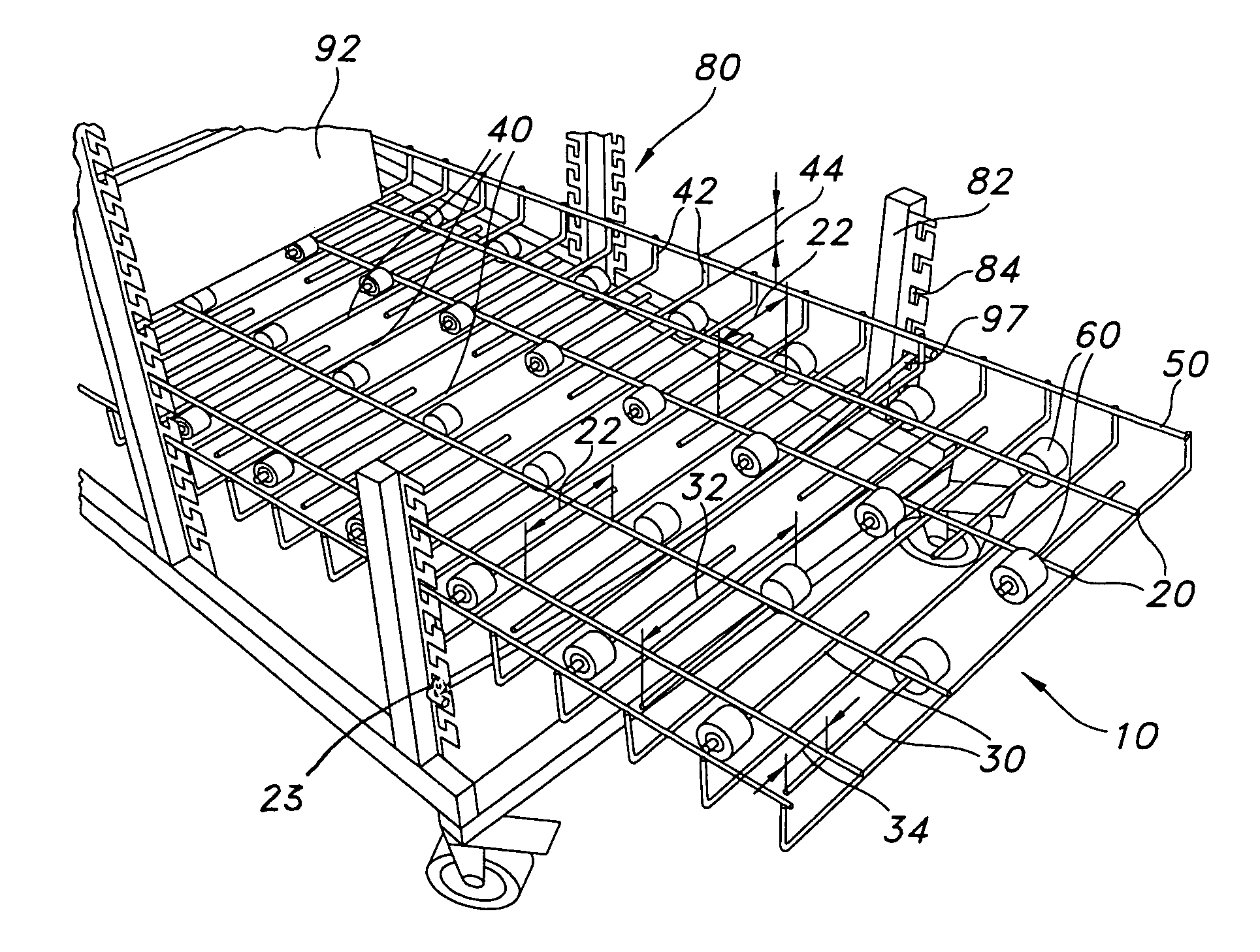
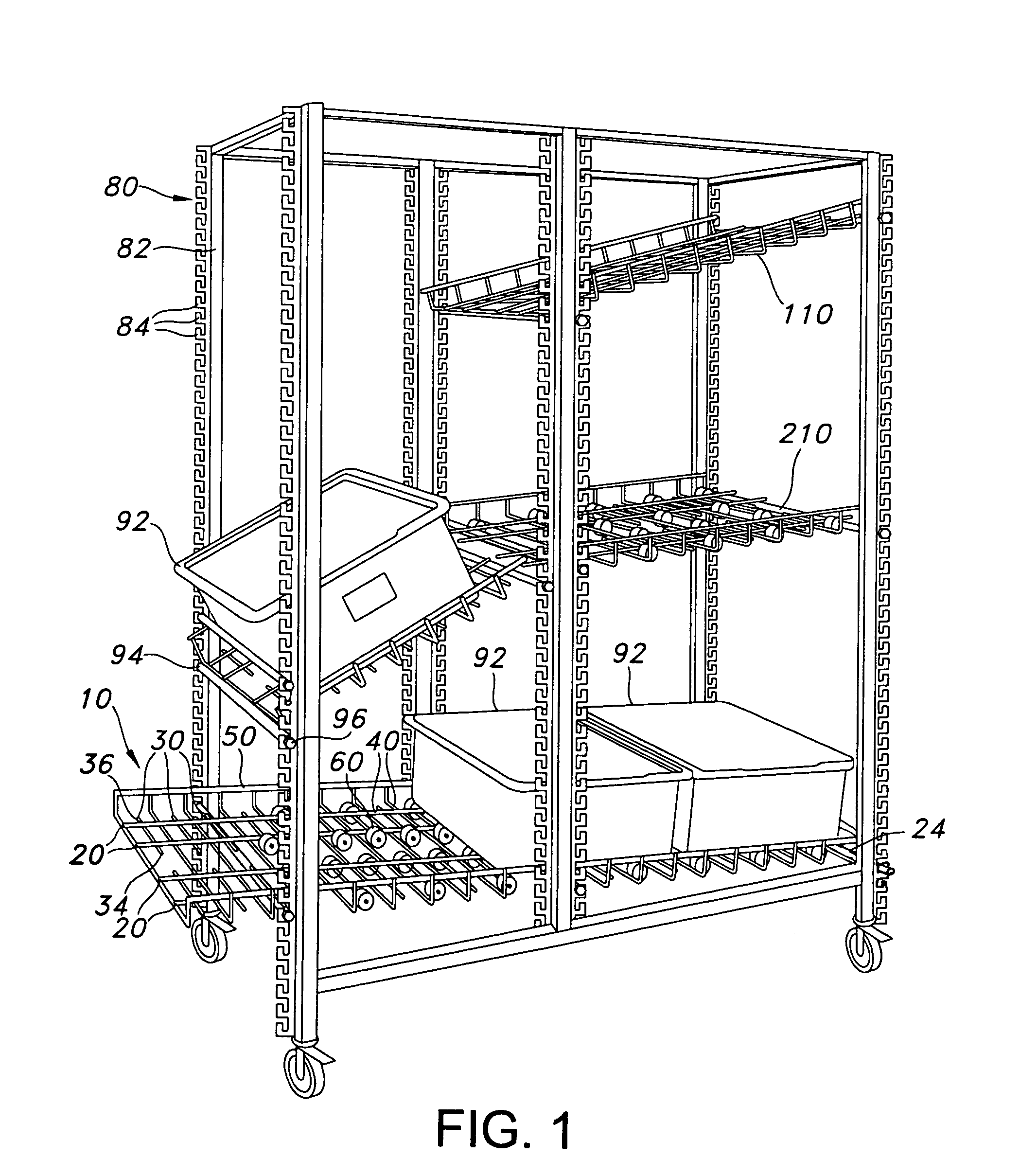
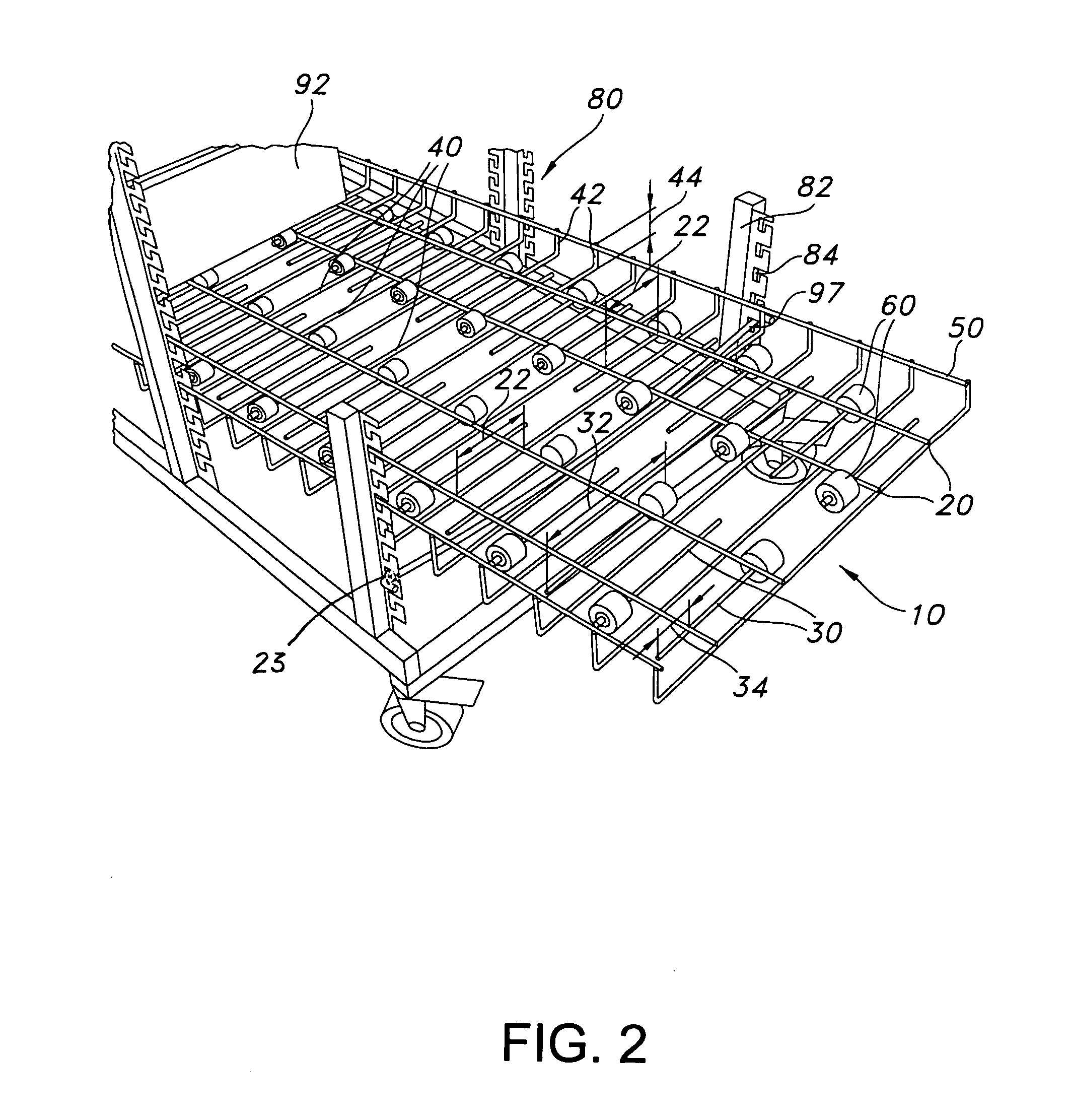
[0017]A flow rack incorporating a preferred embodiment of the present invention is shown in FIG. 1 and generally designated 10. The flow rack includes longitudinal wires 20, roller wires 30 and rollers 60. Optional transverse wires 40 can include upwardly bent ends that are further joined with optional bumper wires 50. The flow rack 10 is shown in FIG. 1 as being incorporated into a support structure 80, however, it will be appreciated that the flow rack is well suited for a variety of other types of shelving and rack systems.

[0018]Other configurations of the flow rack 110 and 210 are also illustrated in FIG. 1, for example, the flow rack 110 illustrates an embodiment of the flow rack in which no rollers are included on the rack. The flow rack 210 illustrates another of the many different configurations of rollers that are possible with the flow rack.

[0019]The flow rack 10 can be mounted to the support structure 80 in a variety of configurations, for example, in an inclined configur...


PUM


Abstract

A wire flow rack system including a longitudinal wire, a roller wire, a roller and an optional cap. The roller wire is joined with and transverse to the longitudinal wire and includes an unsupported free end that projects beyond the longitudinal wire. The roller defines an axial bore, and is positioned on the free end so that the it is free to rotate about the roller wire. A end element, for example, a cap, can be joined with the free end to prevent the roller from disengaging the free end. The cap can be friction fit with the free end and easily, manually replaceable relative to the free end, without the use of tools.

Description

BACKGROUND OF THE INVENTION[0001]The present invention relates to a flow system, and more particularly to a wire flow rack.[0002]A variety of flow systems exist for handling parts and products in manufacturing, distribution, and retail facilities. Many of these systems transfer items from one location to another under the force of gravity. For example, such systems include inclined shelves having rollers that enable product to be loaded from one side and “flow” via gravity to another side of the system to provide easy access to the product by a laborer or a machine.[0003]One conventional flow rack system, disclosed in U.S. Pat. No. 3,840,102 to Dawson, includes a bed of rollers, with groups of several rollers being supported on a single shaft in spaced apart relation. The shaft is supported on opposite ends, and the middle as well, to add structural support to it when product travels over the rollers.[0004]Although conventional flow rack systems enable the transfer of product from o...

Claims


Application Information

Patent Timeline
IPC IPC(8): B65G1/00B62B3/00B65G1/02B65G13/12B65G41/00
CPCB62B3/002B65G1/023B65G13/12B62B3/02B62B2202/12B62B2203/74
Inventor NEUMAN, LARRY D.
Owner LIFE TIME SYST
Why Eureka
Try Eureka