MCU control for brushless DC motor

Active Publication Date: 2005-09-27
SILICON LAB INC
View PDF7 Cites 47 Cited by
  • Summary
  • Abstract
  • Description
  • Claims
  • Application Information

AI Technical Summary

Benefits of technology

[0004]The present invention disclosed and claimed herein, in one aspect thereof, comprises a processor for controlling a sensorless, brushless DC motor. The processor includes a first output for providing a control signal to a potentiometer that controls the speed and voltage of the DC motor. A first input of the processor receives a back-EMF voltage from an open phase of a three phase winding. The processor is able to determine a digital error signal from the back-E

Problems solved by technology

One of the major barriers limiting the market penetration of brushless DC motors has been the cost of the Hall-Effect sensors in brushless DC motors.
However, the Hall-Effect assembly adds significant expense to the cost of manufacturing the motor.
Hall-Effect transistors also typically require five additional wires which add to t

Method used


Image

  • MCU control for brushless DC motor
  • MCU control for brushless DC motor
  • MCU control for brushless DC motor

Examples


Embodiment Construction

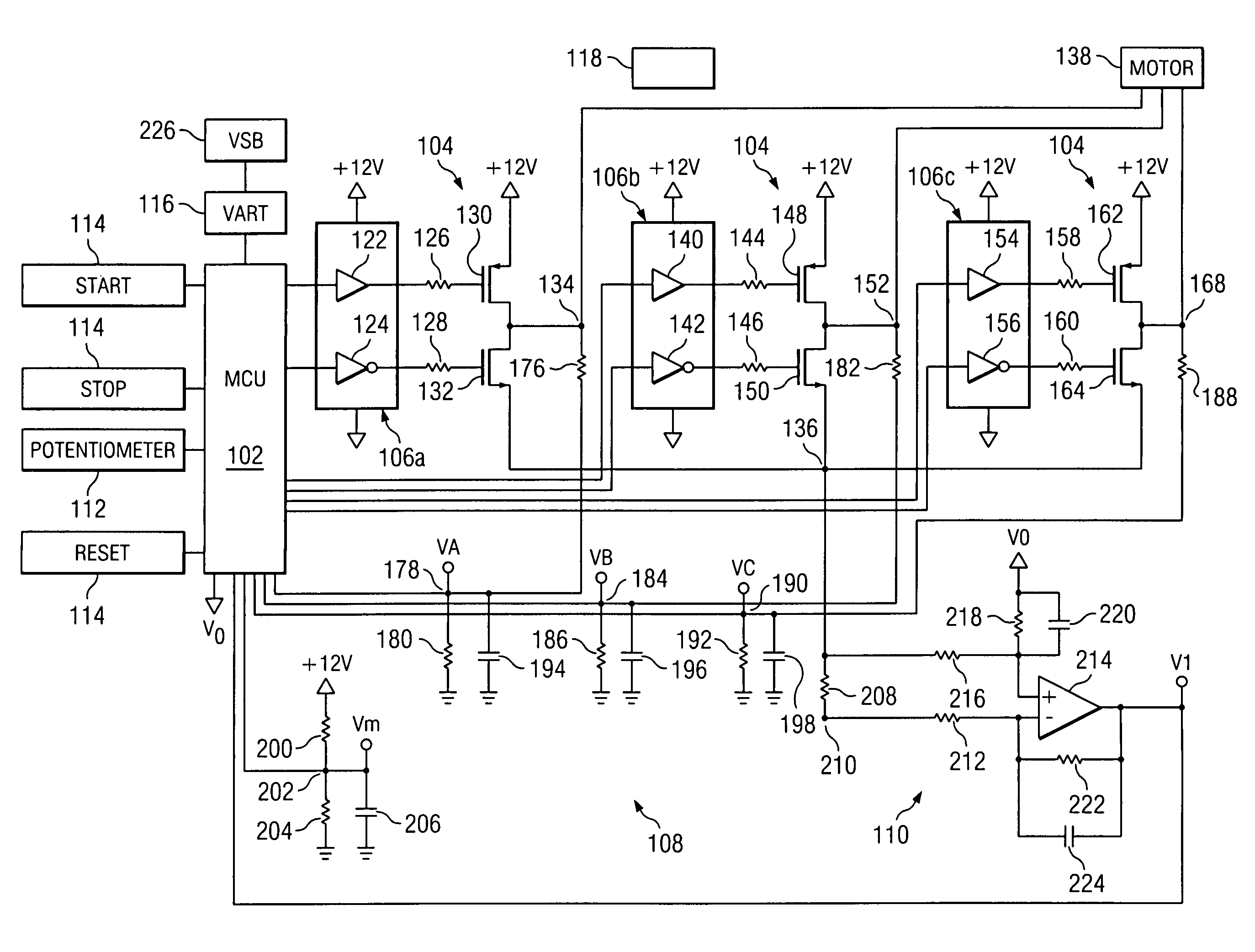
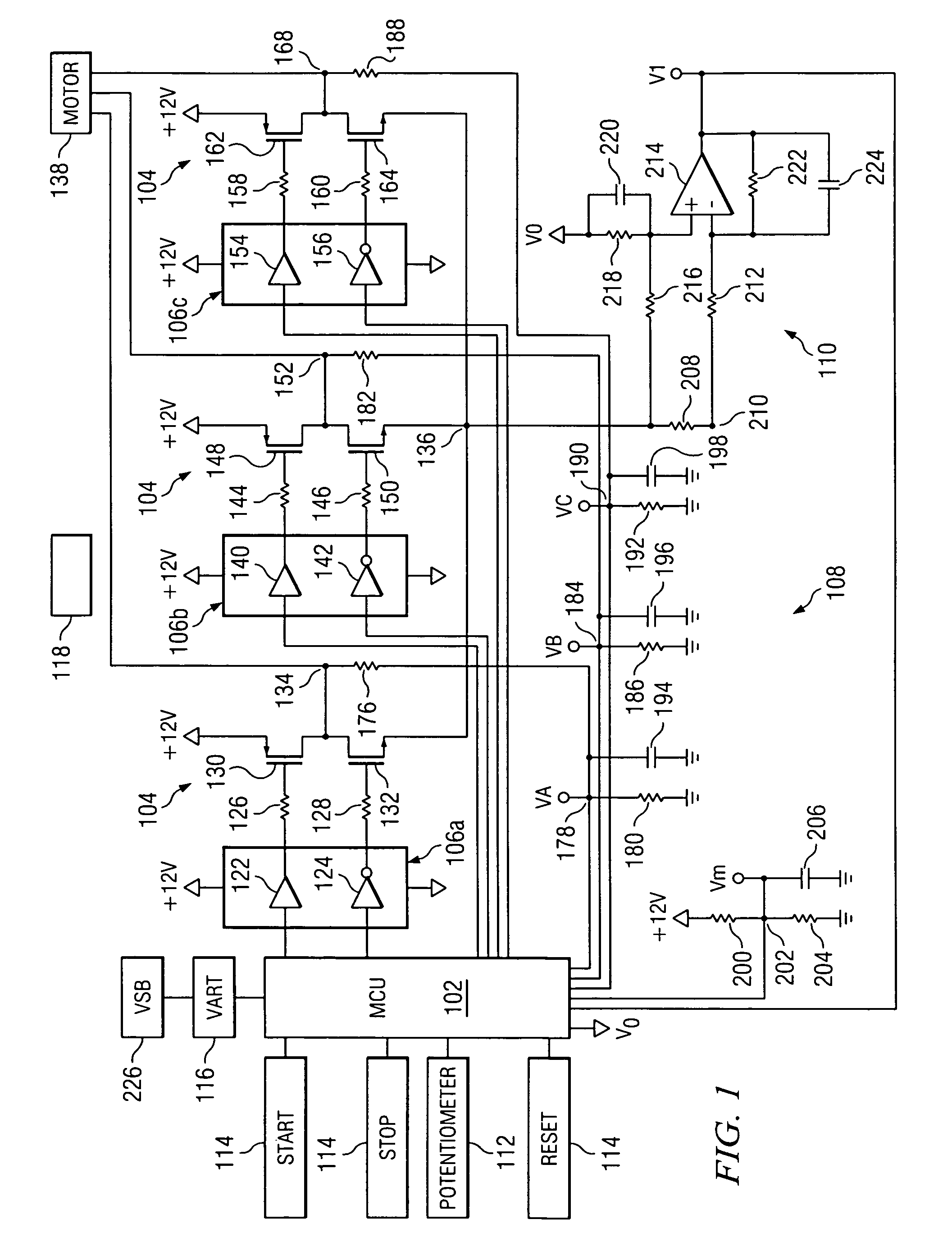
[0017]Referring now to the drawings, and more particularly to FIG. 1, there is illustrated a schematic diagram of a sensorless, brushless DC motor according to the present disclosure. Sensorless, brushless DC motors may be utilized in a number of devices. For example, most computer hard disk drives use a sensorless, brushless DC motor. However, these small motor drives use a linear regulator to control the voltage applied to the motor. While this solution works well for small motors, it is inefficient to use for motors of greater than a few watts. Larger motors require PWM control for efficient operation. Using PWM control makes the task of measuring the back-EMF of the motor more difficult.

[0018]Sensorless, brushless DC motors are well suited for fans and rotary pumps from a few watts up to about 1 kW. Fans and pump loads are predictable and fairly well behaved. Most sensorless, brushless DC motors do not provide the same level of dynamic speed control available from Hall-Effect co...


PUM


Abstract

A processor for controlling a sensorless, brushless DC motor is disclosed comprising a first output for providing a control signal to a potentiometer controlling the speed and voltage of the DC motor. The processor also includes a second input for receiving a back-EMF voltage from an open phase of a three phase winding. The processor determines a digital error signal from the back-EMF voltage and generates a control signal responsive to the digital error signal. The control signal decreases the speed of the motor when the digital error signal is in a first range. The processor decreases both the speed and voltage of the motor when the digital error signal is in a second range. The processor increases the speed of the motor when the digital error signal is in a third range. The processor increases both the speed and voltage of the motor when the digital error signal is in a fourth range.

Description

TECHNICAL FIELD OF THE INVENTION[0001]The present invention relates to sensorless and brushless DC motors, and more particularly, to a method for controlling a sensorless and brushless DC motor using a single MCU based control loop.BACKGROUND OF THE INVENTION[0002]Brushless DC motors consist of a permanent magnet rotor with a three phase stator winding. Brushless DC motors evolved from conventional DC motors where the function of the brushes is replaced by electronics. Brushless DC motors offer longer life and less maintenance than conventional brush DC motors. Most brushless DC motor designs use Hall-Effect sensors to measure the position of the rotor. Hall-Effect sensors provide the absolute position information required to commutate the motor. Using Hall-Effect sensors provides simple, robust commutation and performance roughly comparable to a brushed DC motor. One of the major barriers limiting the market penetration of brushless DC motors has been the cost of the Hall-Effect se...

Claims


Application Information

Patent Timeline
IPC IPC(8): H02P7/06
CPCH02P6/08H02P6/165H02P6/182H02P6/17
Inventor BERRINGER, KENNETH ALAN
Owner SILICON LAB INC
Why Eureka
Try Eureka