

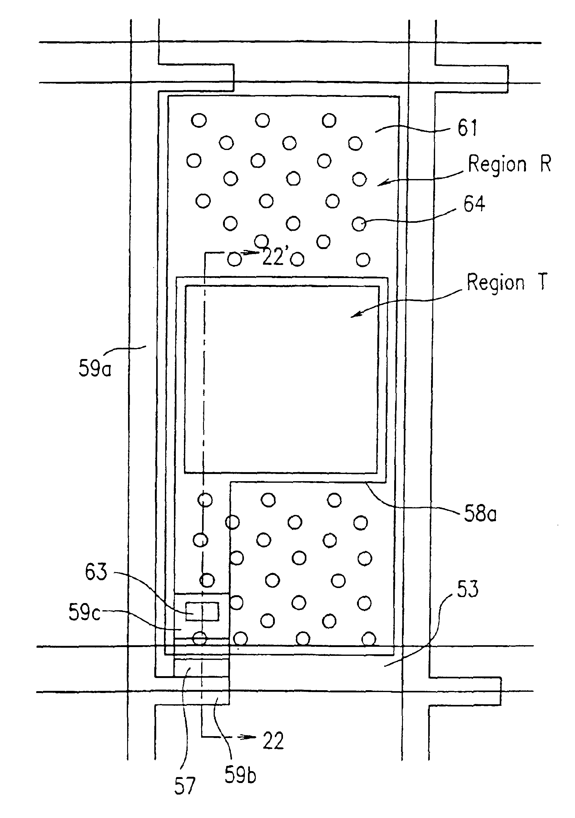
Transflective LCD device having less distance between transmission region and first bus line than transmission region and second bus line
a technology of liquid crystal display device and transmission region, which is applied in non-linear optics, instruments, optics, etc., can solve the problems of not performing satisfactory black display, unable to achieve sufficient contrast ratio, and usually consuming 50% or more of the total power consumption of lcd device backligh
- Summary
- Abstract
- Description
- Claims
- Application Information
AI Technical Summary
Benefits of technology
Problems solved by technology
Method used
Image

Examples
embodiment 1
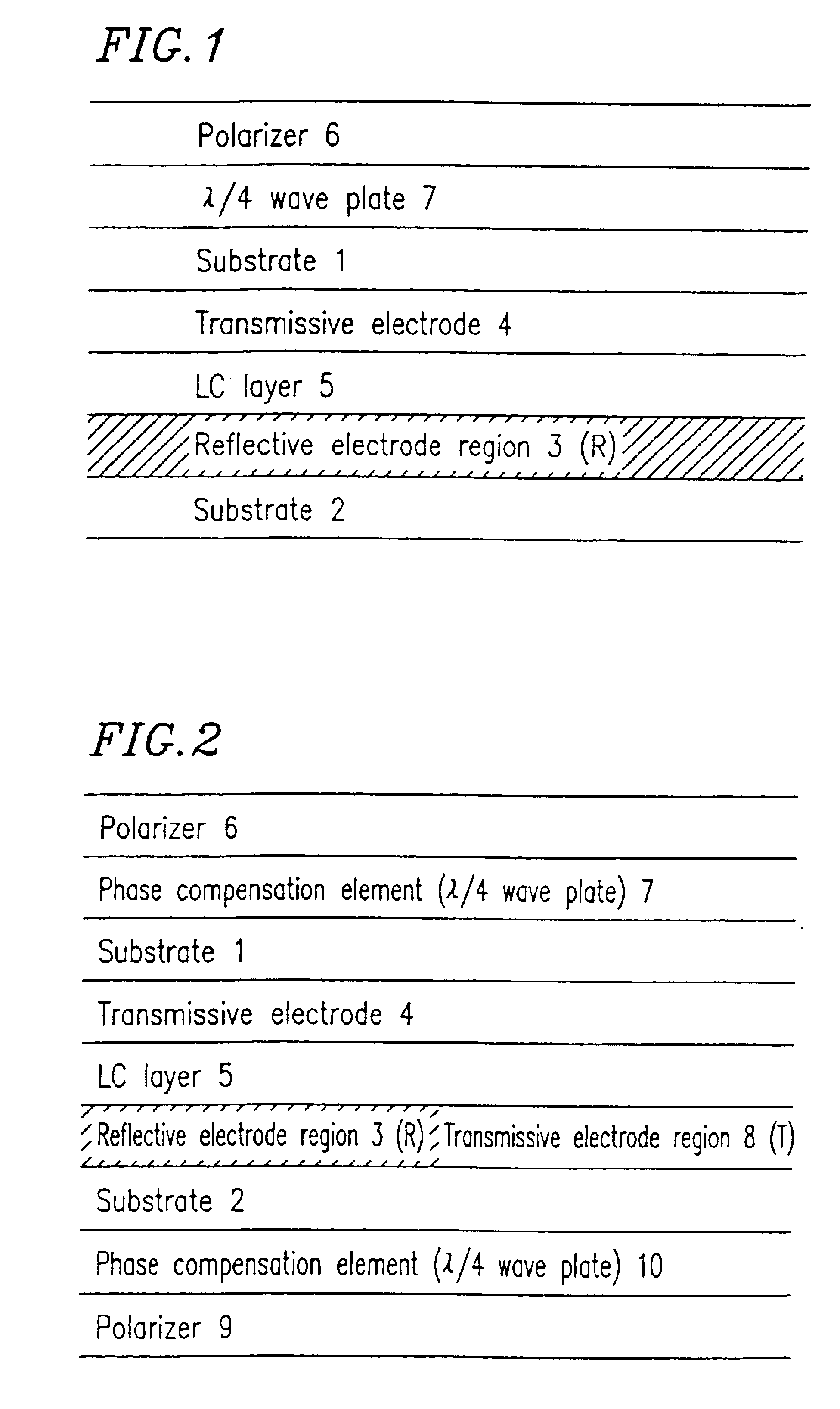
[0100]In a first embodiment of the present invention, a reflection-type LCD device having a higher display quality than the conventional LCD device is provided as specifically described in a first example. A reflection-type LCD device in the first embodiment, as shown in FIG. 1, includes a first substrate 1 including a transmissive electrode 4, a second substrate 2 including a reflective electrode region 3, a liquid crystal layer 5 interposed between the first substrate 1 and the second substrate 2, a polarizer 6 provided on a surface of the first substrate 1 opposite to the liquid crystal layer 5, and a λ / 4 wave plate 7 provided between the polarizer 6 and the liquid crystal layer 5. FIG. 1 schematically shows one pixel area of the reflection-type LCD device according to the present invention.
[0101]The liquid crystal layer 5 includes liquid crystal molecules (not shown) exhibiting negative dielectric anisotropy. The liquid crystal molecules in the liquid crystal layer 5 are substan...
example 1
[0140]An LCD device in a first example according to the present invention will be described with reference to FIG. 1.
[0141]A substrate 2 includes a reflective electrode 3 (shown as reflective electrode region in FIG. 1) formed of a material having a high reflectance such as, for example, Al or Ta. A substrate 1 includes a counter electrode 4 (shown as transmissive electrode in FIG. 1). A liquid crystal layer 5 formed of a liquid crystal material exhibiting negative dielectric anisotropy is interposed between the reflective electrode 3 and the counter electrode 4.
[0142]Alignment layers (not shown) are provided on surfaces of the reflective electrode 3 and the counter electrode 4 which are in contact with the liquid crystal layer 5. The alignment layers are used to align liquid crystal molecules (not shown) in the liquid crystal layer 5 to be vertical to the surfaces of the substrates 1 and 2. After the alignment layers are provided, at least one of the alignment layers is processed w...
example 2
[0189]An LCD device in a second example according to the present invention will be described with reference to FIG. 2. Identical elements as those in the first example bear identical reference numerals.
[0190]A substrate 2 includes a reflective electrode 3 (shown as reflective electrode region in FIG. 2) formed of a material having a high reflectance such as, for example, Al or Ta and a transmissive electrode 8 (shown as transmissive electrode region in FIG. 2) formed of a material having a high transmittance such as, for example, ITO. A substrate 1 includes a counter electrode 4 (shown as transmissive electrode in FIG. 2). A liquid crystal layer 5 formed of a liquid crystal material exhibiting negative dielectric anisotropy is interposed between the reflective electrode 3 / transmissive electrode 8 and the counter electrode 4.
[0191]Alignment layers (not shown) are provided on surfaces of the reflective electrode 3 / transmissive electrode 8 and the counter electrode 4 which are in conta...
PUM
| Property | Measurement | Unit |
|---|---|---|
| angle | aaaaa | aaaaa |
| wavelength | aaaaa | aaaaa |
| tilt angle | aaaaa | aaaaa |
Abstract
Description
Claims
Application Information