Vacuum generator in combustion engine

Inactive Publication Date: 2005-10-04
ADVICS CO LTD
View PDF9 Cites 43 Cited by
  • Summary
  • Abstract
  • Description
  • Claims
  • Application Information

AI Technical Summary

Benefits of technology

[0009]Briefly, in a vacuum generator in a combustion engine according to the present invention, an idling air passage incorporating an idle speed control valve for controlling the idling rotational speed of the combustion engine is connected to a suction pipe to bypass a throttle valve arranged in the suction pipe. The vacuum generator is provided with conduit means for leading the intake negative pressure of the combustion engine to a negative pressure device through a check valve. The vacuum generator is further provided with an ejector for permitting a part of the intake air volume toward the combustion engine to flow therethrough thereby to generate a negative pressure at a vacuum takeout port thereof, and the negative pressure generated at the vacuum takeout port is utilized to increase the absolute value of the negative pressure led to the negative pressure device. The ejector is arranged in the idling air passage at the downstream of the idle speed control valve in serial relation to the same so that the air flow from an inflow port to an outflow port of the ejector is inhaled into the combustion chamber of the combustion engine.
[0010]With this configuration, the intake negative pressure of the combustion engine is led to the negative pressure device through the check valve. In the idling air passage which is connected to the suction pipe of the combustion engine to bypass the throttle valve, the ejector is arranged at the downstream of the idle speed control valve in serial relation to the same, and air intake for

Problems solved by technology

This causes an actual intake air volume to vary with respect to the opening degree of the throttle valve which is to attain a desired intake air volume of the combustion engine, so that a prob

Method used


Image

  • Vacuum generator in combustion engine
  • Vacuum generator in combustion engine
  • Vacuum generator in combustion engine

Examples


Embodiment Construction

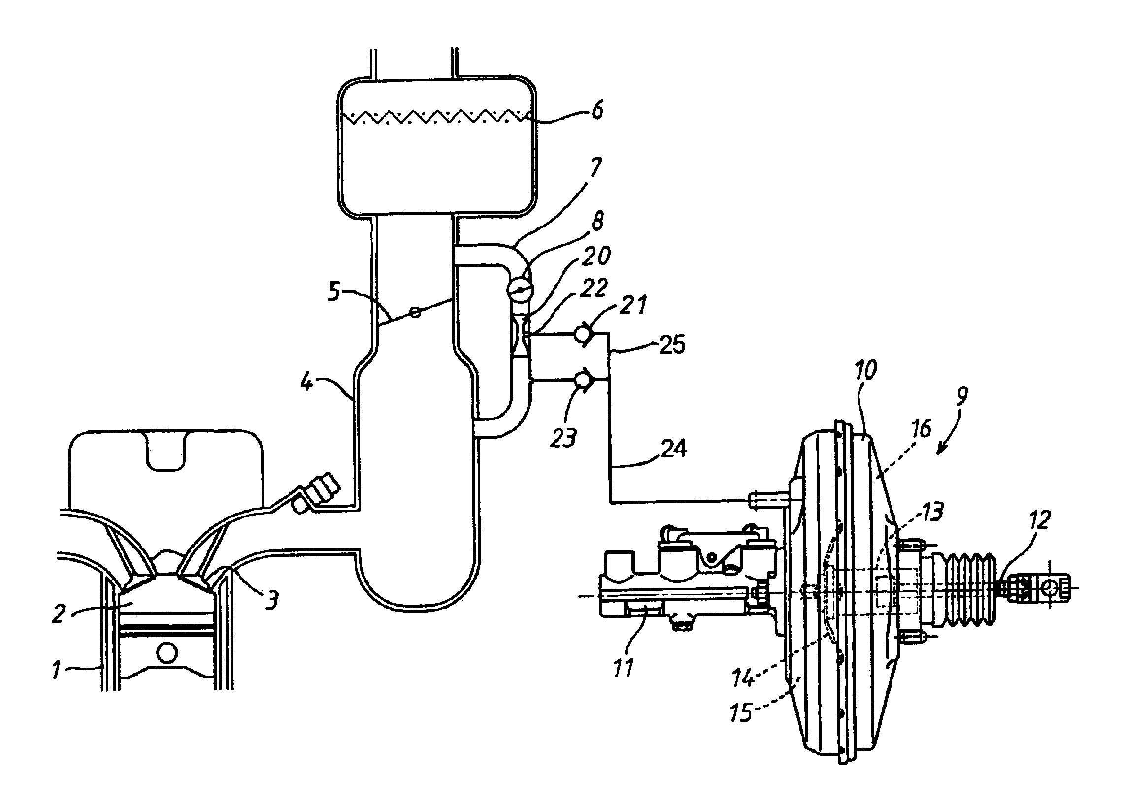
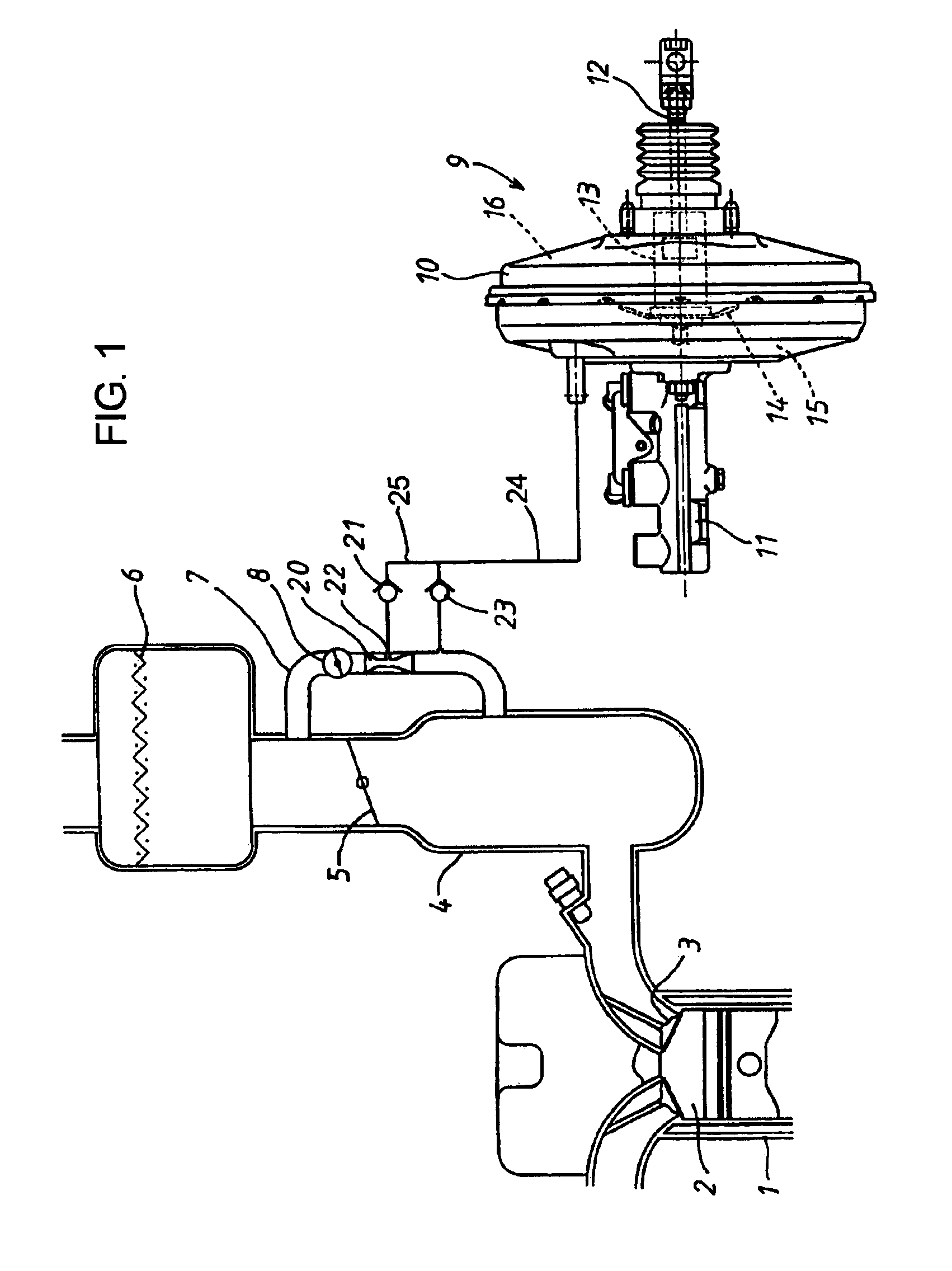
[0015]A vacuum generator in one embodiment according to the present invention will be described hereinafter with reference to the accompanying drawings. Referring now to FIG. 1 schematically showing an engine intake system, a numeral 1 denotes a combustion engine having combustion chambers 2 (one only shown), each of which is connected to a suction pipe 4 through an intake valve 3. At a throttle valve section of the suction pipe 4, there is provided with a throttle valve 5, whose opening degree is controllable by a throttle actuator (not shown) in dependence on the driving state of the engine. The suction pipe 4 opens to the atmosphere through a filter element 6. A numeral 7 denotes an idling air passage, which is connected to the suction pipe 4 at the upstream and downstream of the throttle valve 5 to bypass the same. The idling air passage 7 incorporates therein an idle speed control valve (ISCV) 8 for controlling the intake air volume when the engine 1 remains in the idling opera...


PUM


Abstract

A vacuum generator is provided wherein the intake vacuum of a combustion engine is led to a negative pressure device such as a vacuum booster of a brake booster device through a check valve. An idling air passage is connected to a suction pipe of the combustion engine to bypass a throttle valve arranged in the suction pipe. An ejector is arranged in the idling air passage at the downstream of an idle speed control valve in serial relation to the same, and the intake for idling is performed through the ejector. As the intake air flow passing through the idling air passage increases, the intake negative pressure which is generated at a vacuum takeout port of the ejector is further increased in absolute value, whereby the negative pressure device has a negative pressure which is further increased in absolute value.

Description

INCORPORATION BY REFERENCE[0001]This application is based on and claims priority under 35 U.S.C. sctn. 119 with respect to Japanese Application No. 2003-75549 filed on Mar. 19, 2003, the entire content of which is incorporated herein by reference.BACKGROUND OF THE INVENTION[0002]1. Field of the Invention[0003]The present invention relates to a vacuum generator for leading an intake negative pressure of a combustion engine to a negative pressure device and for increasing the vacuum pressure in the negative pressure device with another negative pressure which is generated at a vacuum takeout port of an ejector through which a part of the intake air to the engine flows.[0004]2. Discussion of the Related Art[0005]Generally, in a vacuum generator incorporated in a combustion engine of this type, the downstream of a throttle valve arranged in a suction pipe of the combustion engine is connected through a check valve to a negative pressure chamber of a vacuum booster incorporated in a brak...

Claims


Application Information

Patent Timeline
IPC IPC(8): B60T17/02B60T13/46B60T17/00F02M69/30F02M69/32F02M23/00F02M23/08F02M35/10F04F5/20
CPCB60T13/46B60T17/02F02M23/085F02M35/10229F02M69/32Y02T10/146Y02T10/12
Inventor SUZUKI, KIMIYASU
Owner ADVICS CO LTD
Why Eureka
Try Eureka