Cover for air bag device

a technology for air bags and covers, applied in the direction of transportation and packaging, pedestrian/occupant safety arrangements, vehicular safety arrangements, etc., can solve the problems of emblems being loose from the cover, complicated procedures, etc., and achieve the effect of improving work efficiency and reliably preventing loosening

Inactive Publication Date: 2005-10-04
JOYSON SAFETY SYST JAPAN KK
View PDF27 Cites 44 Cited by
  • Summary
  • Abstract
  • Description
  • Claims
  • Application Information

AI Technical Summary

Benefits of technology

[0011]In the cover for the air bag device, after the extension is extended through the hole of the cover and is bent, the extension is fixed by means of welding. This secures the emblem to the cover. This facilitates attachment of the emblem to the cover. Further, the extension is covered by the welding body to prevent the extension from directly contacting the emblem. In addition, since the extension is fixed by the welding body, the emblem is prevented from becoming loose.
[0024]In this case, if a projection abutting against a front side of the cover projects from an outer periphery of the cover, the emblem is reliably prevented from becoming loose in a direction perpendicular to the front side of the cover (attaching direction).

Problems solved by technology

Since the distal ends are relatively small, the procedure is extremely complicated.
Further, in the above emblem attaching structure, the projections may become loose in the holes, causing the emblem to become loose from the cover.

Method used


Image

  • Cover for air bag device
  • Cover for air bag device
  • Cover for air bag device

Examples


Embodiment Construction

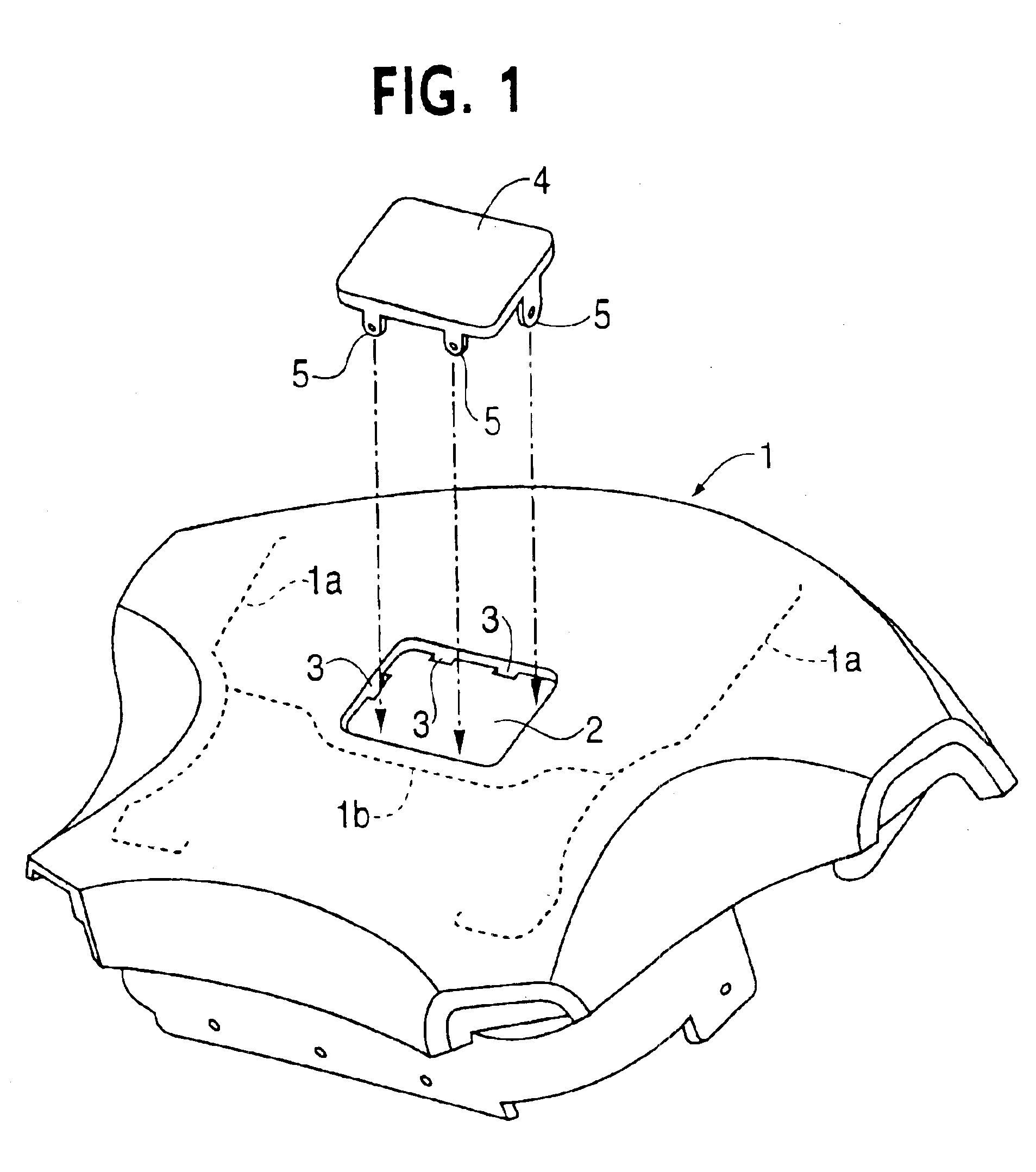
[0073]As described further below, the present invention secures an emblem to a cover firmly and easily. An embodiment of the present invention will now be described with reference to the accompanying drawings.

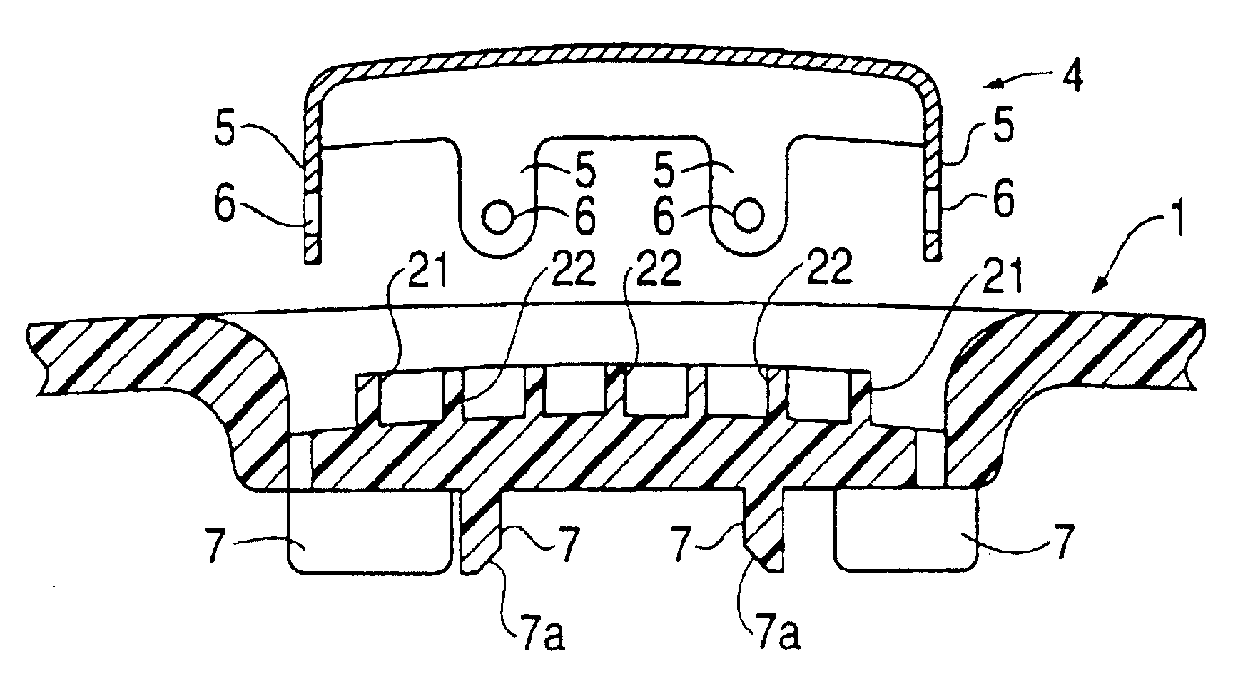
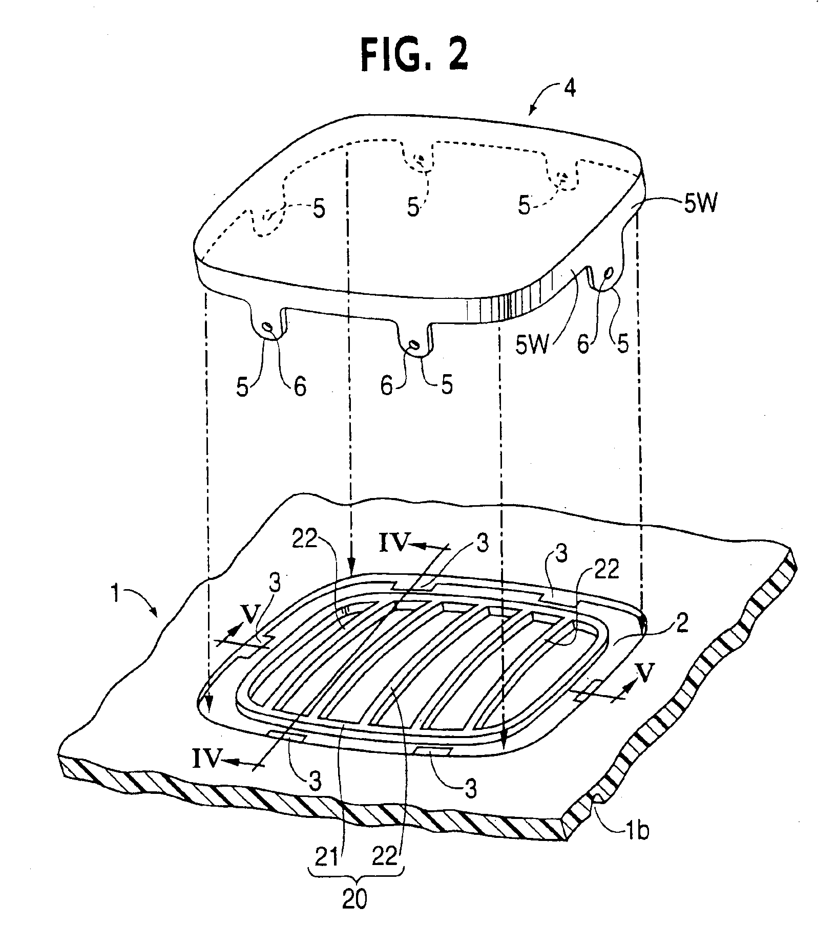
[0074]A cover 1 is a module cover for a driver seat air bag device and is located in the middle of a steering wheel facing the driver. The cover 1 is formed of, for example, thermoplastic synthetic resin through injection molding. As shown in FIG. 1, a pair of tearing lines 1a, 1b are formed in an inner side of the cover 1. When an air bag is inflated, the cover 1 is ruptured along the tearing lines 1a, 1b. A recess 2 is provided in a front side of the cover 1 for receiving an emblem 4.

[0075]As shown in FIG. 1, the emblem 4 may be substantially rectangular with the recess 2 having the same shape. However, it is obvious that the emblem 4 is not restricted to this shape. A plurality of holes 3 are provided along a side wall of the recess 2. The holes 3 extend through the cover 1,...


PUM

PropertyMeasurementUnit
speedaaaaaaaaaa
structureaaaaaaaaaa
softaaaaaaaaaa

Abstract

A cover for an air bag device that enables an emblem to be secured to the cover in an extremely simple manner. The cover (module cover) has a recess for receiving the emblem. An extension of the emblem is extended through a hole in the cover. A distal end of the extension is bent along a rear side of the cover. A rib is pressed and welded by a thermal or ultrasonic welding element to form a welding body. The welding body covers the distal end of the extension.

Description

CROSS-REFERENCE TO RELATED APPLICATIONS[0001]This application is a divisional application of U.S. application Ser. No. 09 / 731,988, filed Dec. 8, 2000, now U.S. Pat. No. 6,692,016, and also claims the benefit of and priority to U.S. Provisional Patent Application Ser. No. 60 / 185,743 entitled “A Structure for Mounting an Emblem on a Steering Wheel”, filed Feb. 29, 2000.BACKGROUND OF THE INVENTION[0002]The present invention relates to covers for air bag devices that protect passengers of high speed moving bodies, such as vehicles, and more particularly, to covers having an emblem. More specifically, the present invention relates to an improved structure for attaching the emblem in the cover.[0003]Air bag devices, such as driver seat air bag devices and passenger seat air bag devices, are widely used to protect passengers from the impact produced during a vehicle collision. A driver seat air bag device is typically mounted on a boss of a steering wheel and includes a gas injecting infla...

Claims


Application Information

Patent Timeline
Patent Type & Authority Patents(United States)
IPC IPC(8): B29C45/14B60R21/20B60R13/00B60K37/00B60R21/203B60R21/215B60R21/2165B62D1/04B62D1/11
CPCB29C45/14311B60R13/005B60R21/215B60R21/21656B29C45/14221B29K2705/00B60R2021/21543
Inventor YOKOTA, KEISHIIGAWA, TADAHIROKOBAYASHI, ICHIZO
Owner JOYSON SAFETY SYST JAPAN KK
Why Eureka
Try Eureka