Adaptive small-signal compensation for switching regulators

Active Publication Date: 2005-10-04
NAT SEMICON CORP
View PDF12 Cites 45 Cited by
  • Summary
  • Abstract
  • Description
  • Claims
  • Application Information

AI Technical Summary

Problems solved by technology

However, non-ideal switching times for transistors Q1 and Q2 may result in unequal cycle times such that the transformer core is driven into saturation.
Core saturation in a PWM converter may result in secondary effects such as breakdown in the switching transistors (Q1, Q2), excessive voltage and current stress on the rectifier diodes (D1, D2), as well as EMI related problems.

Method used


Image

  • Adaptive small-signal compensation for switching regulators
  • Adaptive small-signal compensation for switching regulators
  • Adaptive small-signal compensation for switching regulators

Examples


example regulator

System

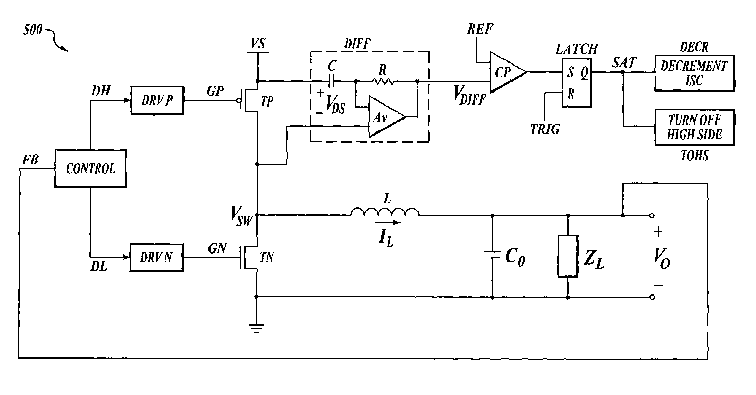
[0042]FIG. 7 illustrates an example regulator system (700) that is arranged according to an aspect of the present invention. The example regulator system includes an inductor (L), a capacitor (C), a load (ZL), a switch circuit, a control circuit, and a feedback circuit. Inductor L is arranged to store energy that is delivered to the load when activated by the switch circuit. The switch circuit is responsive to drive signals that are provided by the control circuit. The feedback circuit is arranged to sense the output voltage of the regulator. The control circuit and the feedback circuit are arranged to cooperate with one another to control the charging cycle time of the inductor to maintain proper regulation.

[0043]In operation, the control circuit and / or the feedback circuit are responsive to a measurement signal (V1). The measurement signal (V1) is related to one or more parameters associated with the inductor (e.g., an inductance value). Regulator system 700 has a loop trans...

example adjustable resistance

Circuit

[0048]FIG. 9 illustrates a schematic diagram (900) for an example adjustable resistor circuit (830) that is arranged according to an aspect of the present invention. The adjustable resistor circuit (830) includes two resistors and a transistor. The transistor and the first resistor are series coupled to one another to form a first resistance circuit between terminals A and B. The second resistor is series coupled between terminals A and B to operate as a second resistance circuit. The overall resistance between the two terminals (A and B) corresponds to the parallel combination of the two resistance circuits.

[0049]The first resistor has a value corresponding to Ra, while the second resistor has a value corresponding to Rb. In operation, a control signal (VC) is applied to the control terminal of the transistor such that the series resistance associated with the transistor is adjusted. In one example, the transistor's series resistance varies over an approximate range of open ...


PUM


Abstract

A system, method, and apparatus are arranged to provide small-signal compensation in a switching regulator that includes an inductor. A zero adjustment circuit is included in the system to introduce at least one zero in the closed-loop transfer function associated with the regulator. The zero adjustment circuit is responsive to a measurement signal, which is associated with one or more measured parameters associated with the inductor. By changing the location of at least one zero in response to the measurement signal it is possible to dynamically change the compensation based on variations in the inductance of the inductor. The zero adjustment circuit may be provided as a portion of the controller block of the regulator, or as a separate feedback circuit. The zero adjustment circuit can be implemented digitally as a portion of a DSP block, or as an analog function as may be desired in a particular system.

Description

RELATED APPLICATION[0001]This patent application is a continuation-in-part of U.S. patent application Ser. No. 10 / 703,960, which was filed Nov. 7, 2003, and claims the benefit under 35 U.S.C. 120 of the filing date.FIELD OF THE INVENTION[0002]The present invention relates to a system and method for adaptively adjusting the small-signal compensation in a switching regulator such as a buck regulator, a boost regulator, or a buck-boost regulator.BACKGROUND OF THE INVENTION[0003]Opposite polarity pulses can be applied to a transformer in a pulse-width-modulated (PWM) power converter. The secondary winding of the transformer is connected to additional circuitry such as a passive filter to generate an average output voltage. The average output voltage is related to the pulse-width by the volts-seconds rule and the characteristics of the transformer.[0004]An example push-pull type PWM converter is illustrated in FIG. 1. As illustrated in FIG. 1, transformer T1 conducts current (IC1, IC2) f...

Claims


Application Information

Patent Timeline
IPC IPC(8): G01R1/04G01R1/02G01R27/00G01R27/28G05F1/10G05F1/40G05F1/656H02M3/156
CPCH02M3/156Y10S323/901
Inventor BROACH, MICHAEL EUGENEDE STASI, FRANK JOHN
Owner NAT SEMICON CORP
Why Eureka
Try Eureka