Liquid crystal display device and its drive method

a display device and liquid crystal technology, applied in static indicating devices, instruments, non-linear optics, etc., can solve the problems of slow response speed, restricted use, slower than the tn mode liquid crystal panel, etc., and achieve superior response characteristics and reduce response time

Inactive Publication Date: 2005-10-04
SHARP KK
View PDF7 Cites 29 Cited by
  • Summary
  • Abstract
  • Description
  • Claims
  • Application Information

AI Technical Summary

Benefits of technology

[0019]According to the present invention, when the liquid crystal in the pixel is changed from the first transmittance to the third transmittance much greater than that, as the second target drive voltage in correspondence with the third transmittance is applied in the first period, it is possible to reduce the response time without causing the overshoot with respect to the change in the alignment of the liquid crystal. Accordingly, it is possible to provide the liquid crystal display device which is free of flicker due-to the overshoot, and has the superior response characteristic.

Problems solved by technology

However, the TN mode liquid crystal mode has drawbacks that a viewing angle is narrower than CRT, etc., and for this reason there is a problem that the use is restricted.
However, in the MVA liquid crystal panel, there is a problem that a response speed when a black state at a drive voltage of about 1V is switched to a low brightness halftone state at a drive voltage of about 2 to 3V is slower than the TN mode liquid crystal panel.
Furthermore, when the black state at the drive voltage of about 1V is switched to a high brightness halftone state at the drive voltage of about 3 to 4V, or when the black state at the drive voltage of about 1V is switched to a white state at the drive voltage of about 5V, as the brightness is overshot, there is a problem that a display impression is worse.

Method used


Image

  • Liquid crystal display device and its drive method
  • Liquid crystal display device and its drive method
  • Liquid crystal display device and its drive method

Examples


first embodiment

[First Embodiment]

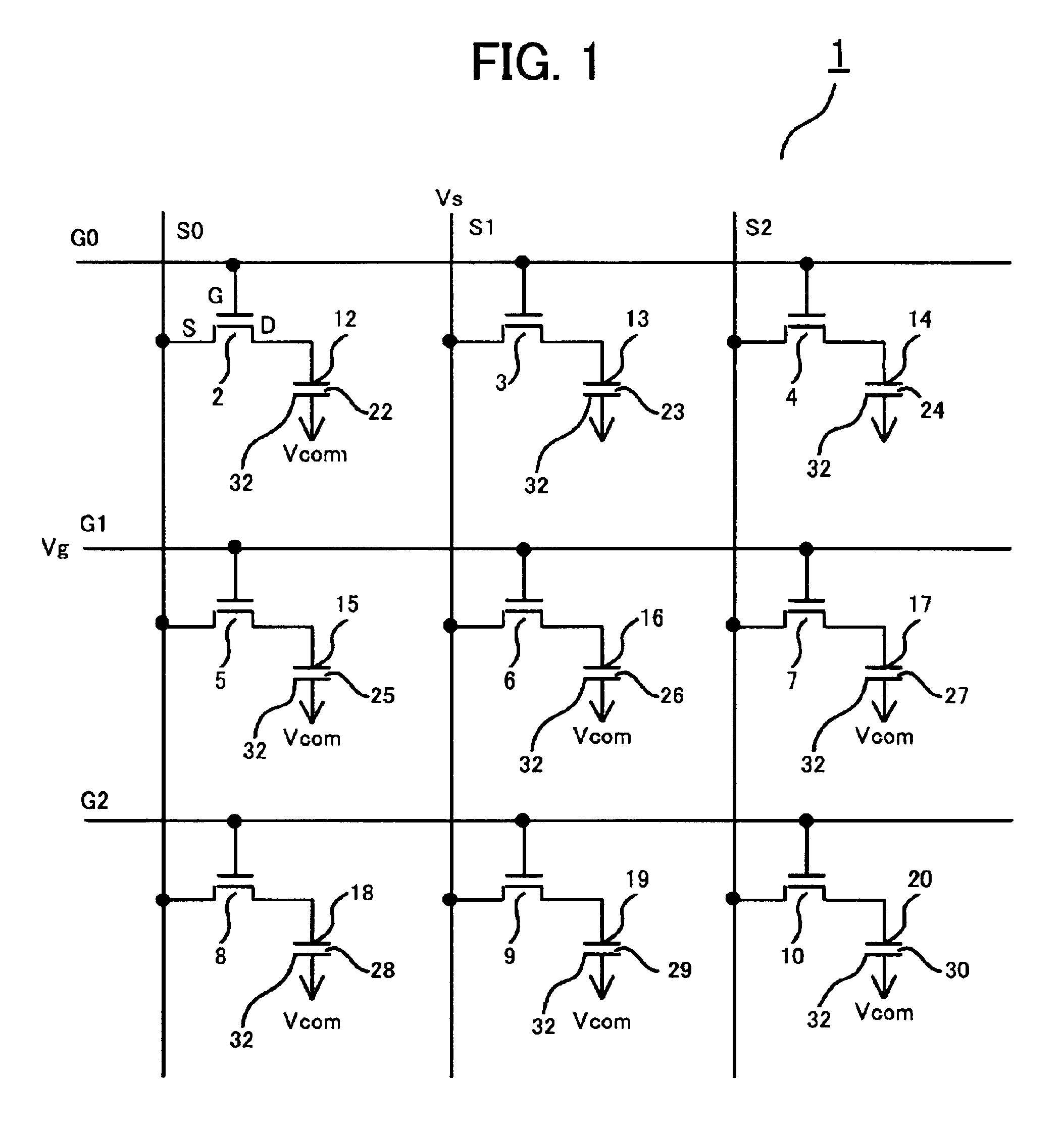
[0047]FIG. 1 is an equivalent circuit of a MVA type liquid crystal panel 1 according to an embodiment of the present invention. The actual MVA type liquid crystal panel 1 has 1024×3×768 pixels, for example, when a color display is made, but here shows the case of 3×3 pixels.

[0048]The MVA type liquid crystal panel 1 is assorted into respective pixels by longitudinal source electrode lines S0, S1, S2 and transverse gate electrode lines G0, G1, G2, and has TFTs 2 to 10 in each of respective pixels. A source electrode S and a gate electrode G of the TFTs 2 to 10 are connected to the source electrode lines S0 to S2 and the gate electrode lines G0 to G2, respectively, and a drain electrode D is connected to pixel electrodes 12 to 20.

[0049]The pixel electrodes 12 to 20 are transparent electrodes of ITO (Indium Tin Oxide), etc., and a drive voltage is applied on liquid crystal pixels 22 to 30 inserted between the pixel electrode and a counter common electrode 32. The commo...

second embodiment

[Second Embodiment]

[0089]Next, a liquid crystal display device according to another embodiment of the present invention in which, in displaying a black, a predetermined drive voltage is applied on liquid crystal molecules to be in advance inclined, so that a response time is lessened when the black state is switched to a halftone state, etc., will be explained.

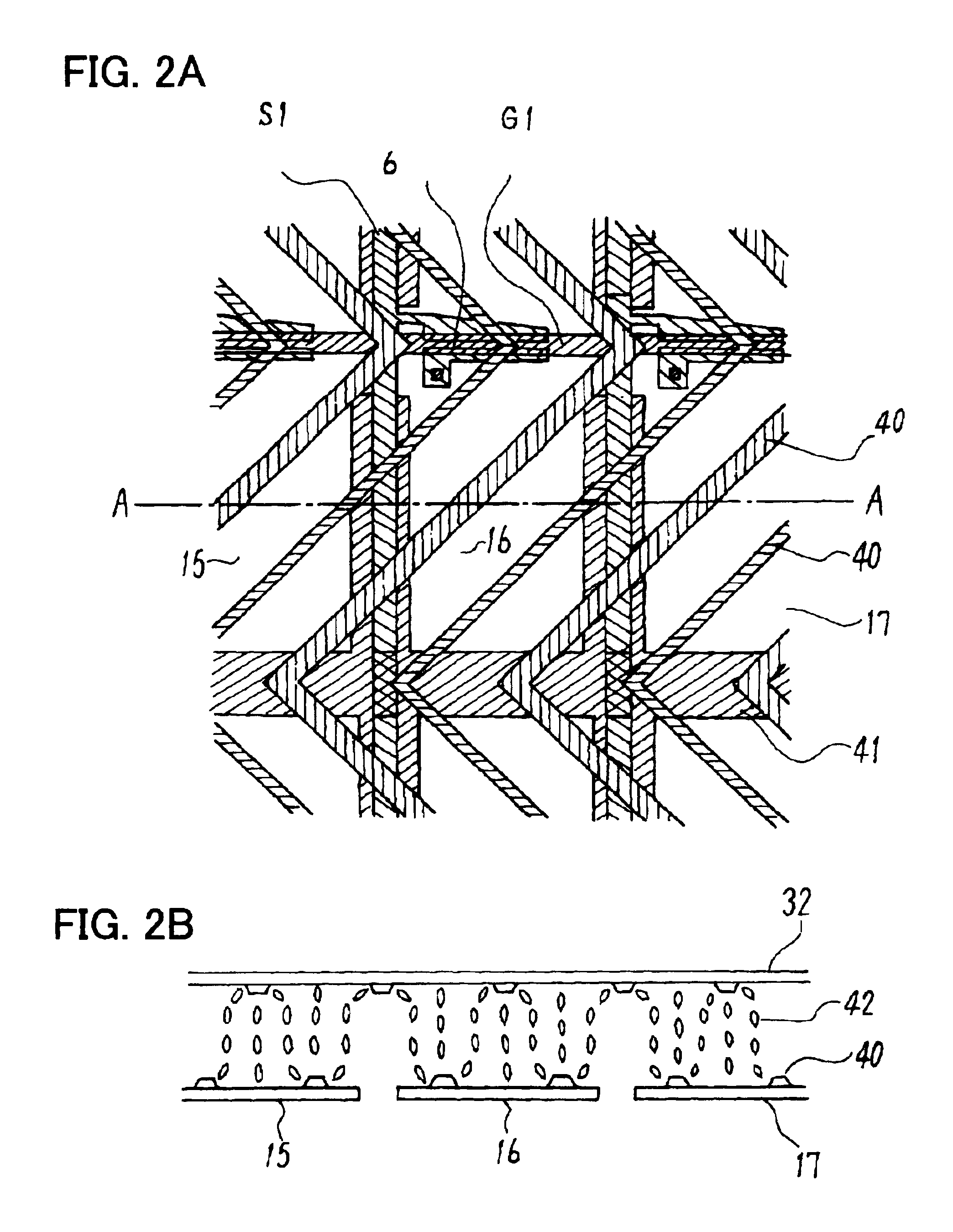
[0090]As described above, as the liquid crystal molecules in the vicinity of a projection of a MVA type liquid crystal panel are aligned vertically to an inclined plane of the projection, the liquid crystal molecules have a slight inclined angle even in a state that a drive voltage is not applied. However, the inclination of the liquid crystal molecules in the vicinity of the projections only becomes a trigger which lets the other liquid crystal molecules incline sequentially when the drive voltage is applied, and the liquid crystal molecules away from the projections are aligned substantially vertically to a substrate in a st...

third embodiment

[Third Embodiment]

[0114]Next, an explanation will be for a liquid crystal display device in which a response time is shortened when a black state is switched to a halftone state, etc., and a liquid crystal display device which reduces an overshoot of a brightness to be generated when the display is switched.

[0115]According to the first embodiment above, when the black state is switched to the halftone state, etc., for example, the black state of one frame just before switching to the halftone state is detected, and a drive voltage of a liquid crystal is adjusted by the detection results. However, since a response characteristic from the black state to the halftone state, etc. is affected by not only the black state of the just preceding one frame, but also the display of the frame further before the just preceding frame, a suitable drive cannot be made by detecting only the black state of the just preceding frame, and there may be a case where an overshoot is generated in a brightne...


PUM

PropertyMeasurementUnit
drive voltageaaaaaaaaaa
voltageaaaaaaaaaa

Abstract

A MVA type liquid crystal panel is slow in a response speed when a black state at a drive voltage about 1V is switched to a low brightness halftone state at the drive voltage about 2 to 3V. According to the present invention, in a liquid crystal display device for driving the MVA type liquid crystal panel, when a liquid crystal pixel at a pixel electrode is changed from a first transmittance to a second transmittance greater than the first transmittance, a drive voltage greater than a first target drive voltage in correspondence with a second transmittance is applied to the pixel electrode in a first frame period of changing to the second transmittance, and the first target display voltage is applied from a second frame period. According to the present invention, even when either switching is performed from a black state to a low brightness halftone state, from the black state to a high brightness halftone state, or from the black state to a white state, a response time is shortened, and the switching can be performed without generating an overshoot.

Description

CROSS REFERENCE TO RELATED APPLICATION[0001]The present application is a continuation of International Application number PCT / JP99 / 06189, filed Nov. 5, 1999, the entire contents of which are herein incorporated by the reference.TECHNICAL FIELD[0002]The present invention relates to a liquid crystal display device and its drive method, and in particular to the liquid crystal display device in which a liquid crystal having minus dielectric constant anisotropy is aligned vertically when non-voltage is applied; and its drive method.BACKGROUND ART[0003]At present, in a liquid crystal panel which carries out active matrix drive by use of a thin film transistor (hereinafter called TFT), its mainstream is a TN (Twisted Nematic) mode liquid crystal panel in which a p type liquid crystal having positive dielectric anisotropy is aligned horizontally to a substrate when non-voltage is applied, and is driven vertically to the substrate when voltage is applied.[0004]With the progress of late manuf...

Claims


Application Information

Patent Timeline
Patent Type & Authority Patents(United States)
IPC IPC(8): G02F1/13G02F1/139G09G3/36G02F1/1343G02F1/133G09G3/20
CPCG02F1/1393G09G3/3648G02F1/134336G09G2310/06G09G2320/0252G09G2320/041G09G2340/16G02F1/133
Inventor OHMURO, KATSUFUMITAKEDA, ARIHIROCHIDA, HIDEONAKAMURA, KIMIAKIKOIKE, YOSHIO
Owner SHARP KK
Why Eureka
Try Eureka