Method for detecting a liquid level in a container in a circuit and a dialysis machine for actuating the method

a liquid level and circuit technology, applied in the direction of volume measurement apparatus/methods, container/cavity capacity measurement, instruments, etc., can solve the problems of inability to provide accurate level readings and become progressively more complicated, and achieve simple and economical equipment and high degree of accuracy.

Inactive Publication Date: 2005-10-11
GAMBRO DASCO SPA
View PDF6 Cites 42 Cited by
  • Summary
  • Abstract
  • Description
  • Claims
  • Application Information

AI Technical Summary

Benefits of technology

[0007]The main aim of the present invention is to provide a level sensor method in a container of a circuit, which method is without the drawbacks inherent in the prior art and which, in particular, provides a high degree of accuracy and requires the use of simple and economical equipment.

Problems solved by technology

This sensor device detects only if the level of blood is above or below the optimal level and is therefore unable to provide an accurate level reading.
The above-described sensor devices are based on the principle of emission and reception of a signal and become progressively more complicated as the need for more accurate blood level readings increases, since the number of emitters and readers increases together with the need for accuracy.

Method used


Image

  • Method for detecting a liquid level in a container in a circuit and a dialysis machine for actuating the method
  • Method for detecting a liquid level in a container in a circuit and a dialysis machine for actuating the method
  • Method for detecting a liquid level in a container in a circuit and a dialysis machine for actuating the method

Examples


example 1

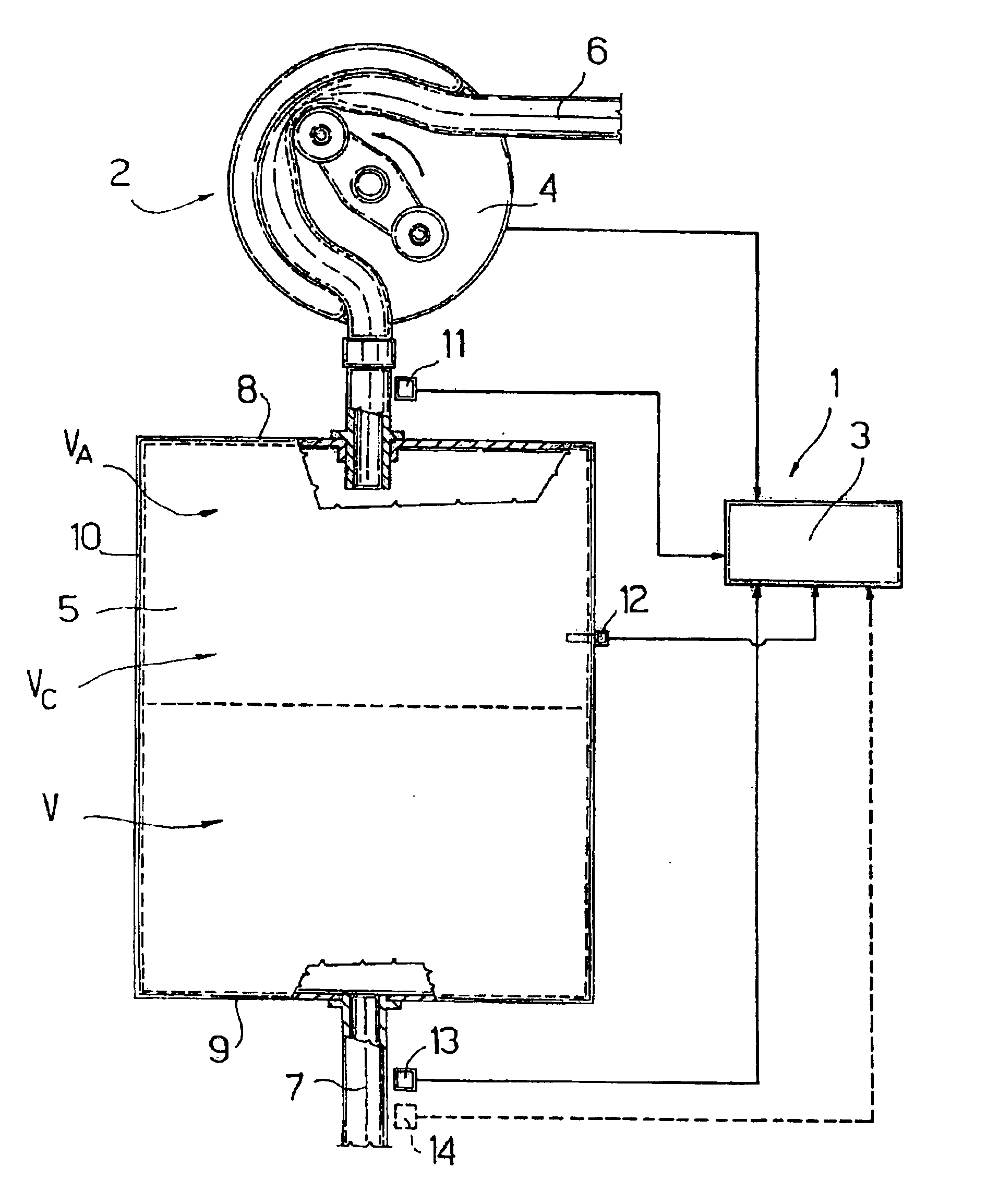
[0025]The container 5 contains, at a determined moment t0, a volume V of blood and the blood inflows at a flow rate Qin by means of the peristaltic pump 4, while outflowing blood from the container 5 occurs at a flow rate Qout. The overall volume of the container 5 is VC, thus the volume VA occupied by the air at t0 is VC−V, while the air pressure at t0 is equal to P0. The peristaltic pump 4 operation modes cause a variation in the inflow flow rate Qin and the outflow flow rate Qout and therefore cause a cyclic variation in the volume V of blood in the container 5. Thus, at a determined moment t1 the change in the blood volume is VD and the following expression of the relations results:

P0(VC−V)=J R T at moment t0

P1(VC−V−VD)=J R T at moment t1

in which the number J of moles of air remains constant, R is a constant, and the temperature T is considered to be constant. From the above expressions the following can be derived:

P0(VC−V)=P1(VC−V−VD)

in which VD=∫t0t1⁢(Qi⁢ ⁢n-Qout)⁢ⅆt

from which...

example 2

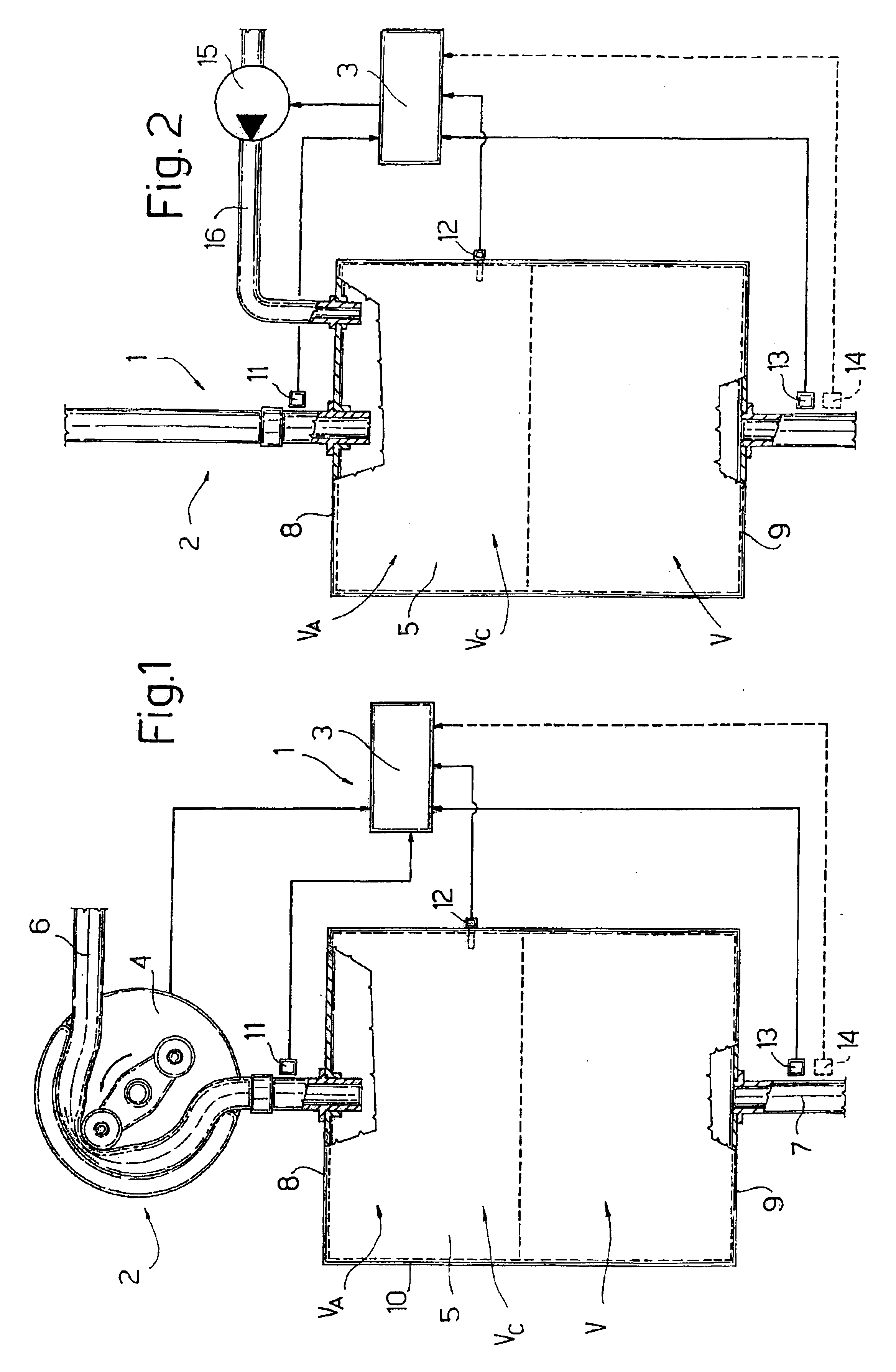
[0031]The container 5 contains a determined volume V of blood which corresponds to a mass M of blood and both the blood supply and evacuation are interrupted. The volume occupied by the air is VA, which corresponds to a mass N of air. The overall volume of the container 5 is VC, therefore the volume occupied by the air is VC−V, while the pressure detected at a determined moment t0 is P0. The slight pressure variations P lead to establish that the temperature T can be considered constant.

[0032]In the above established state, at moment t0 the following is a valid expression:

P0(VC−V)=N0K  a)

[0033]The pump 15 induces a disturbance in the container 5, which is a variation in the mass N0 of air, by injecting a mass DN of air into the container 5, to bring the mass of air up to a level expressed by:

N1=N0+DN.  b)

[0034]The disturbance in the mass of air determines a variation in pressure P inside the container 5. Following the variation in mass, at moment t1 the following is a valid expressi...


PUM


Abstract

A container of a dialysis machine has a determined shape and a known volume occupied in part by a volume of a mass of blood; a remaining part is occupied by a volume of a mass of gas. A disturbance is induced in a combined mass of the liquid and the gas in the container and an entity of the disturbance is measured. Measurements of pressure in the container before and after the disturbance are taken, the volume of gas is calculated using a function correlated to a gas law, and the volume and level of the liquid in the container are derived after the volume occupied by the gas is calculated.

Description

BACKGROUND OF THE INVENTION[0001]The invention relates to a method for detecting a liquid level in a container of a circuit.[0002]In particular, the invention relates to a method for detecting a level of blood in a container of a circuit of a dialysis machine, to which the present application will make specific reference without in any way limiting the scope of the invention.[0003]A known-type dialysis machine comprises a first blood circulation circuit and a second circulation circuit for the dialysate liquid. The first circuit and the second circuit are connected to a filter for conveying, respectively, the blood and dialysate liquid through the filter, which is provided with a semi-permeable membrane separating the blood from the dialysate liquid. The first circuit is provided with a container, known as a drip chamber, into which the blood is supplied from a first tract of the first circuit, and drips and collects on the bottom of the container, thence to enter a second tract of ...

Claims


Application Information

Patent Timeline
Patent Type & Authority Patents(United States)
IPC IPC(8): G01F23/14
CPCG01F23/14A61M1/3624A61M1/3627
Inventor DELNEVO, ANNALISA
Owner GAMBRO DASCO SPA
Why Eureka
Try Eureka