Method for joining a tube to a member

a tube and member technology, applied in the field of joining parts together, can solve the problems of long cycle time between welds, inconsistent welds, and expensive friction welding equipment, and achieve the effect of strong joint and easy joining

Inactive Publication Date: 2005-10-11
DELPHI TECH INC
View PDF35 Cites 9 Cited by
  • Summary
  • Abstract
  • Description
  • Claims
  • Application Information

AI Technical Summary

Benefits of technology

[0011]Several benefits and advantages are derived from one or more of the methods of the invention. The use of a tube flange in joining a tube to a member provides a stronger joint and allows easier joining of thin walled tubes. By applying only local heating proximate the contact of the flange and the member without substantially heating the first tube and / or the member apart from proximate the contact of the flange and the member avoids deformation of the tube (especially a thin-walled tube) and / or member from heating regions not involved in creating the joint.

Problems solved by technology

Gas metal arc welding requires expensive welding equipment, the molten weld puddle tends to flow away from the joint area depending on weld position resulting in welds of inconsistent quality, and the process requires a long cycle time between welds.
Friction welding requires expensive welding equipment, and the process requires a long cycle time between welds.
Also, friction welding may not be applicable if no part to be welded can be rotated.
Conventional methods for attaching a tube to a member further include laser-beam or electron-beam welding together of the abutting ends of two straight tubes or the overlapping ends of two straight tubes which require expensive welding equipment and expensive part geometry tolerances prior to welding.

Method used


Image

  • Method for joining a tube to a member
  • Method for joining a tube to a member
  • Method for joining a tube to a member

Examples


first embodiment

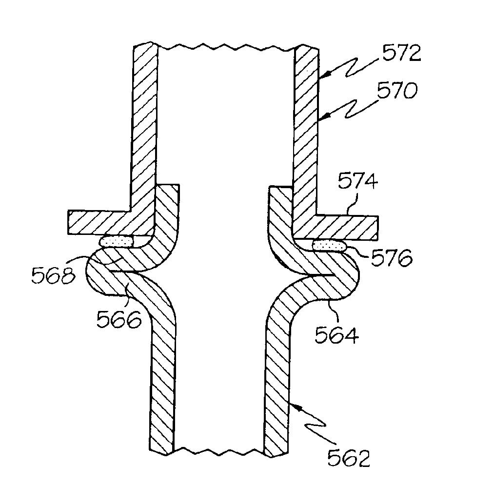
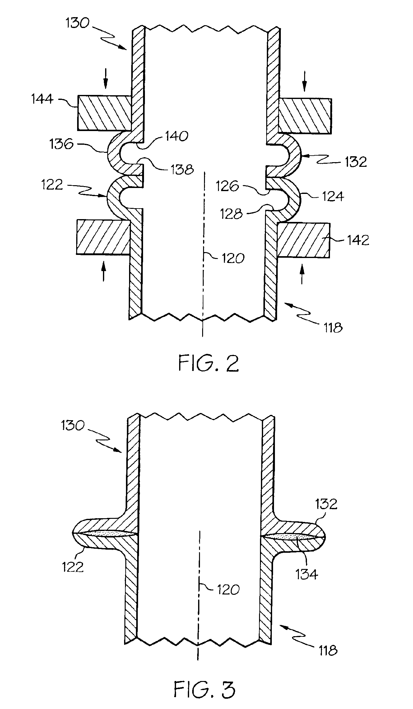
[0032]Referring to FIGS. 2-3, wherein like numerals represent like elements throughout, a second method of the invention is for metallurgically joining one tube to another tube and includes steps a) through d). Step a) includes obtaining a first tube 118 having a longitudinal axis 120 and having a first end portion 122, wherein the first end portion includes a first annular fold 124 substantially coaxially aligned with the longitudinal axis 120, and wherein the first annular fold 124 includes longitudinally-spaced-apart first and second fold portions 126 and 128. Step b) includes obtaining a second tube 130 having a second end portion 132. Step c) includes, after steps a) and b), coaxially aligning the first and second tubes118 and 130 and disposing the first and second tubes 118 and 130 with the first end portion 122 contacting the second end portion 132. Step d) includes, after step c), creating a resistance welding current path through the first and second tubes 118 and 130 proxi...

second embodiment

[0035]In a second example of the second method, and referring to FIG. 4, the second end portion 232 of the second tube 230 is a substantially straight end portion having a substantially-longitudinally-facing annular end 246, wherein the second tube 230 has a greater wall thickness than the first tube 218, and wherein step c) disposes the first and second tubes 218 and 230 with the annular end 246 longitudinally contacting the first annular fold 224. In one application, the second tube 230 is a nut. In one variation, the first annular fold 224 is a radially-outwardly-protruding annular fold. In one implementation, step d) uses an annular resistance-welding first electrode 242 longitudinally contacting the first annular fold 224 and uses a resistance-welding second electrode 244 disposed in radial contact with the second end portion 232. In one modification, the first electrode 242 longitudinally contacts the second electrode 244 at the completion of step d). In one arrangement, a non...

third embodiment

[0036]In an alternate second example of the second method, and referring to FIG. 5, the first annular fold 324 of the first end portion 322 of the first tube 318 protrudes radially outward and longitudinally upward as shown in the figure. The first electrode 342 is disposed outside the first tube 318, and the second electrode 344 is disposed outside the second tube 330. A non-electrode first support 350 is disposed inside the first tube 318 and extends around the other end of the first tube 318, and a non-electrode second support 352 is disposed inside the second tube 330 and extends around the other end of the second tube 330. In one variation, not shown, the positions of the first electrode and the first support are interchanged, and the positions of the second electrode and the second support are interchanged.

[0037]Other embodiments for the second method are left to the artisan. Optional examples, enablements, etc. of the first method applicable to tube-to-tube joining are equall...


PUM

PropertyMeasurementUnit
thicknessaaaaaaaaaa
diameteraaaaaaaaaa
electric currentaaaaaaaaaa

Abstract

A method for joining a tube to a member. A tube having a flange is obtained, and a member is obtained. The tube and the member are positioned with the flange contacting the member either directly or indirectly through an intervening joining material. The tube and / or the member are locally heated proximate the contact of the flange and the member without substantially heating the tube and / or the member apart from proximate the contact of the flange and the member. In one example, the local heating is welding, with or without a filler material, such as resistance welding, laser-beam welding or electron-beam welding. In another example, the local heating is brazing. In an additional example, a curable adhesive joining material is placed on the flange and / or the member, wherein the adhesive is located between and directly contacts the flange and the member, and wherein the local heating cures the adhesive.

Description

CROSS-REFERENCE TO RELATED APPLICATIONS[0001]The present application is a continuation-in-part application of U.S. patent application Ser. No. 10 / 226,179 filed Aug. 22, 2002.TECHNICAL FIELD[0002]The present invention relates generally to attaching parts together, and more particularly to a method for joining a tube to a member.BACKGROUND OF THE INVENTION[0003]Resistance welding (also known as electric-resistance welding) is a known metallurgical process wherein metal is heated by its own resistance to a semi-fused (i.e., soft) or fused (i.e., molten) state by the passage of very heavy electric currents for very short lengths of time and then welded by the application of pressure.[0004]Conventional methods for attaching parts together include gas metal arc welding. Gas metal arc welding uses a consumable metal wire as one electrode and the parts as another electrode, and moves the consumable metal wire (or the parts) to draw an arc and weld the parts together. The welding is accompan...

Claims


Application Information

Patent Timeline
Patent Type & Authority Patents(United States)
IPC IPC(8): B23K26/00B23K26/28B23K11/02B23K11/06B23K33/00F16L13/02F16L13/00
CPCB23K11/02B23K11/066B23K26/28B23K33/002B23K33/006F16L13/02B23K2201/06B23K2101/06
Inventor ANANTHANARAYANAN, VENKATASUBRAMANIANRAMACHANDRA, DHARMENDRA M.MARCZEWSKI, RICHARD W.
Owner DELPHI TECH INC
Why Eureka
Try Eureka