
Vehicle headlamp

a headlamp and headlamp technology, applied in the field of headlamps, can solve the problems of considerable difficulty in meeting these requirements, unable to adequately enhance etc., and achieve the effect of efficient enhancement of the luminosity of the hot zon

Inactive Publication Date: 2005-10-11
KOITO MFG CO LTD
View PDF3 Cites 56 Cited by
  • Summary
  • Abstract
  • Description
  • Claims
  • Application Information

AI Technical Summary

Benefits of technology

[0009]The present invention was made in the view of the foregoing situations, and provides a vehicle headlamp capable of efficiently enhancing the luminosity of the hot zone at the time of high beam irradiation, while still offering glare prevention for the oncoming driver at the time of low beam irradiation. The vehicle headlamp of the invention is configured to execute forward beam irradiation in a predetermined light distribution pattern using the projector-type lamp unit.

Problems solved by technology

As a result, a luminous intensity of a hot zone (area of high-intensity light) cannot be adequately enhanced at the time of high beam irradiation, when a beam switching is executed by shifting the shade.
In the projector-type lamp unit in which a light source image becomes larger, it is considerably difficult to fulfill these requirements by depending only on the absence or presence of a shade to shield the light.

Method used


Image

  • Vehicle headlamp
  • Vehicle headlamp
  • Vehicle headlamp

Examples


Embodiment Construction

[0036]Hereafter, embodiments of the present invention will be described with reference to accompanying drawings.

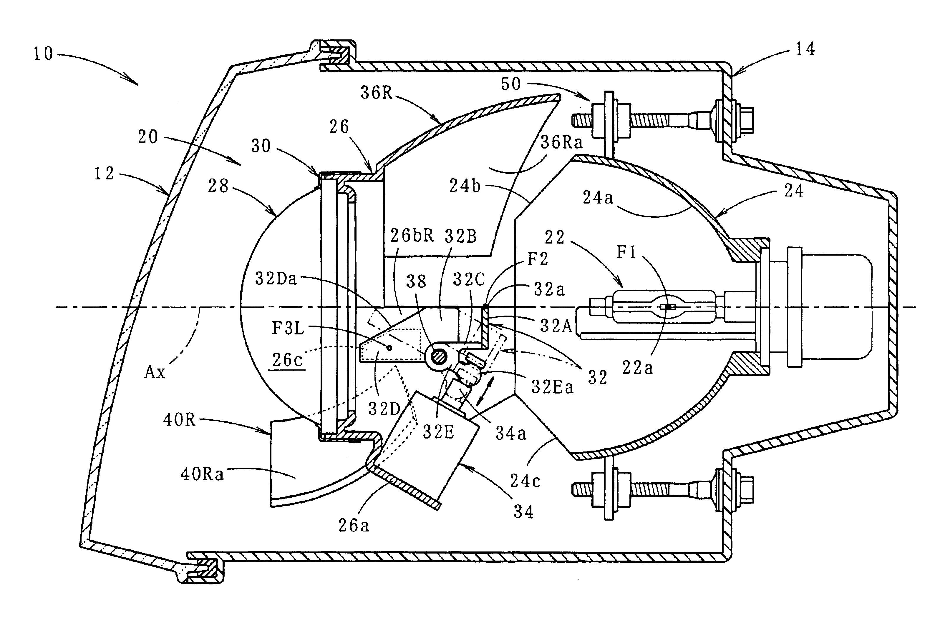
[0037]FIG. 1 is a vertical sectional view showing a vehicle headlamp according to an embodiment of the present invention.

[0038]As shown in the figure, a vehicle headlamp 10 includes a lamp body 14 and translucent cover 12. A lamp unit 20 is tiltable in the vertical and lateral directions through an aiming mechanism 50, in a lamp room formed by the translucent cover 12 and the lamp body 14.

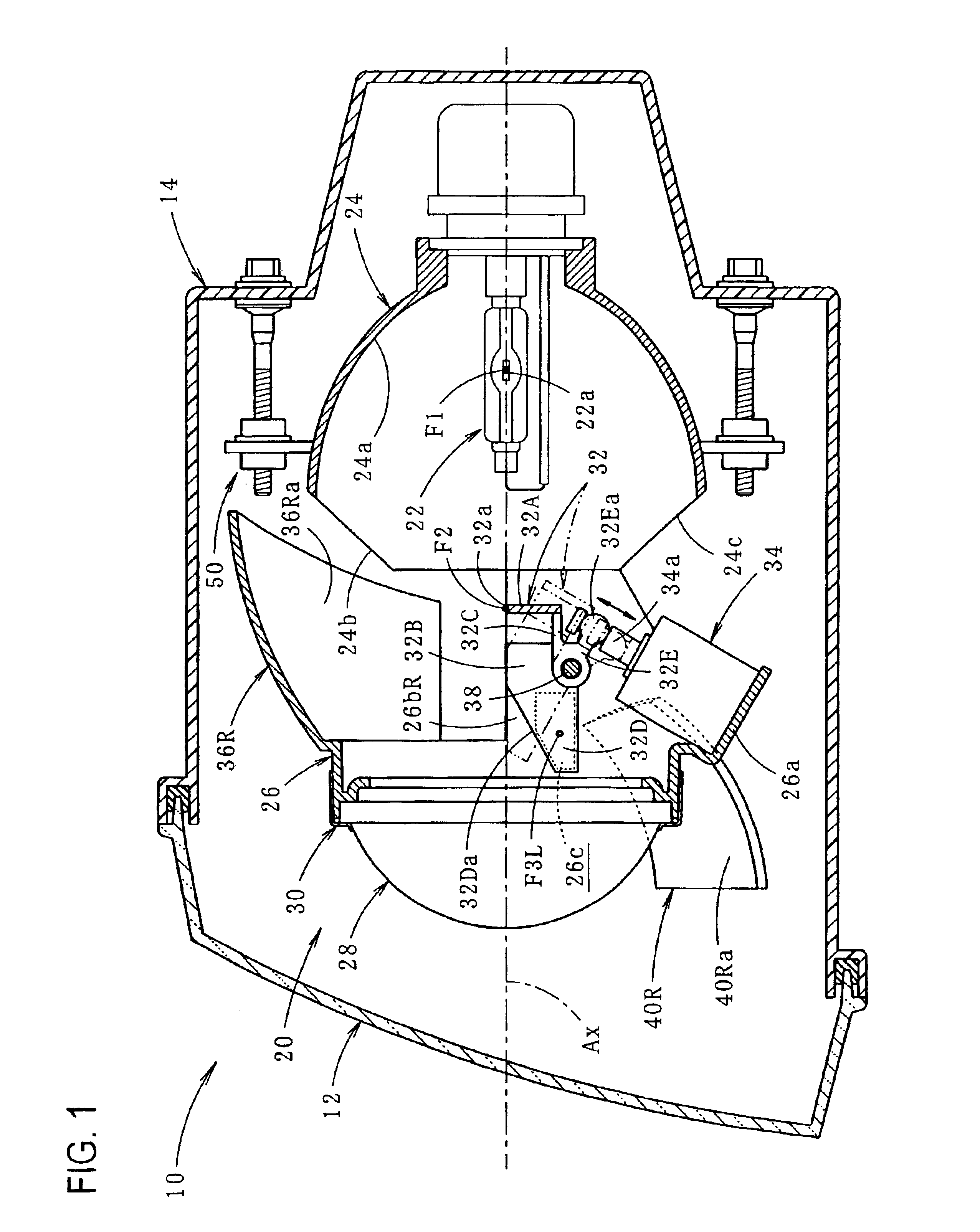
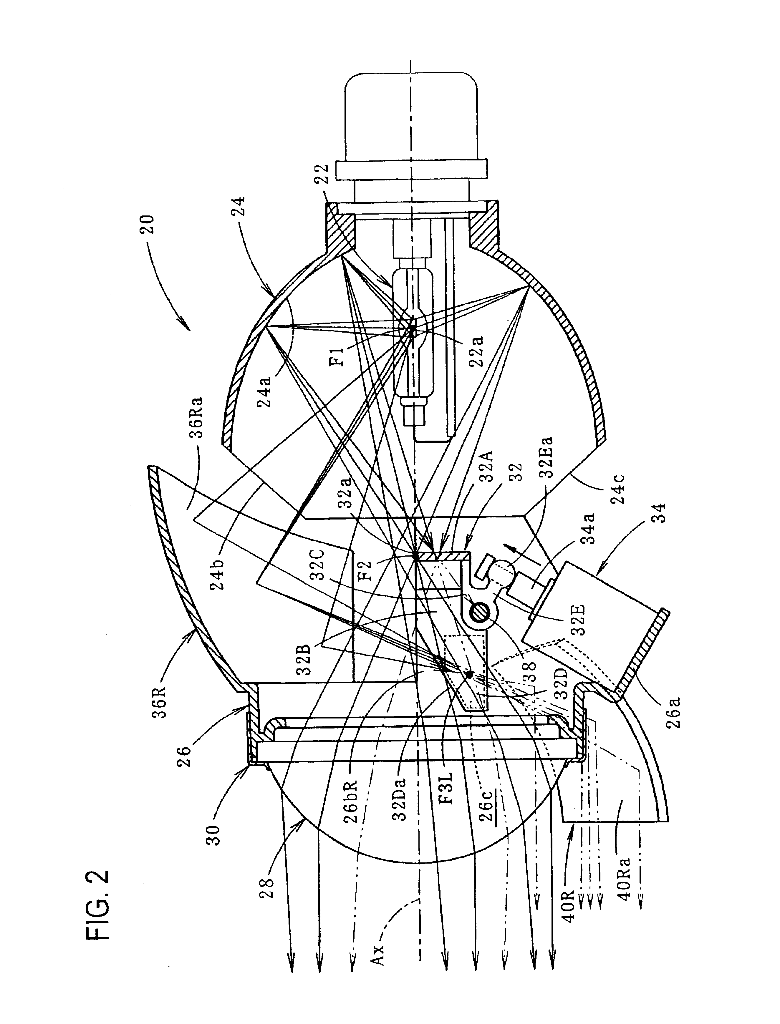
[0039]FIGS. 2 and 3 are vertical sectional views showing the lamp unit 20 alone, and FIGS. 4 and 5 are its horizontal sectional view and front view. Also, FIG. 6 is a perspective view showing major components of the lamp unit 20.

[0040]As shown in these figures, the lamp unit 20 is a projector-type lamp unit including a discharge bulb 22, a reflector 24, a holder 26, a projection lens 28, a shade 32, an actuator 34, first additional reflectors 36L, 36R, and second additional reflectors 40L...


PUM


Abstract

A vehicle headlamp having a projector-type lamp unit that enhances a luminous intensity of a hot zone at the time of high beam irradiation is described. A first additional reflector is provided obliquely left-upward of an optical axis Ax, and a second additional reflector is provided obliquely right-downward of the optical axis Ax, between a reflector and a projection lens. An additional light distribution pattern is formed in a center area of a high beam distribution pattern by reflecting direct light, which has entered the first additional reflector from a light source, obliquely right-downward and then forward by the second additional reflector, at the time of high beam irradiation. A reflective surface of the first additional reflector is formed like an ellipsoid spherical surface having the second focus on the right side with respect to the optical axis A (the second reflector side). This makes the additional light distribution pattern into a pattern with a narrow vertical width, and enhances a luminosity of the hot zone without making a short distance area of a road surface at the front of the vehicle excessively luminous.

Description

TECHNICAL FIELD[0001]The present invention relates to a vehicle headlamp provided with a so-called projector-type lamp unit.BACKGROUND OF THE INVENTION[0002]A vehicle headlamp, which is configured to execute a beam switching between low beam and high beam by shifting a shade, has been previously known. For example, a vehicle headlamp including a beam switching mechanism as above driven by shifting the shade is disclosed in U.S. Pat. No. 6,286,985B1.[0003]Although the beam switching mechanism driven by shifting the shade is employed in a so-called parabola-type lamp unit in the vehicle headlamp disclosed in the above-mentioned publication, it is also possible to employ a beam switching mechanism driven by shifting the shade in the projector-type lamp unit.[0004]However, in the projector-type lamp unit, a light source image that forms a light distribution pattern is larger than that in the parabola-type lamp unit, due to its structural features. As a result, a luminous intensity of a ...

Claims


Application Information

Patent Timeline
Patent Type & Authority Patents(United States)
IPC IPC(8): F21V7/00F21V14/08F21V14/00F21S8/12F21S8/10F21V11/00F21V13/00F21W101/10F21Y101/00
CPCF21S48/1388F21S48/1778F21S41/172F21S41/255F21S41/321F21S41/323F21S41/365F21S41/43F21S41/689
Inventor HAYAKAWA, MICHIHIKOTSUKAMOTO, MICHIO
Owner KOITO MFG CO LTD
Learn More