Water pit transmitter assembly

a transmitter and assembly technology, applied in the field of water pit transmitter assembly, can solve the problems of tampering, false readings, and previous assemblies being subject to detachment, and achieve the effect of preventing frequency detachmen

Inactive Publication Date: 2005-10-11
AMCO AUTOMATED SYST
View PDF31 Cites 46 Cited by
  • Summary
  • Abstract
  • Description
  • Claims
  • Application Information

AI Technical Summary

Benefits of technology

[0007]The assembly typically includes batteries which are placed within the battery compartment of the battery housing. Battery wires connect the batteries to the circuit board transponder. The housing is also typically provided with a data cable. An encoder is usually connected to the water meter. The data cable is connected from the encoder to the circuit board transponder, so the circuit board transponder receives encoded meter readings from the water meter through the data cable. A protective material such as a gel preferably covers the components in the multiple sections of the housing. Plastic shields may cover the transmitter circuitry and both antennas to prevent frequency detuning caused by the protective encapsulating material.
[0010]The controller controls and activates the functions of the assembly. The functions include a low power required sleep-state mode, the normal operating mode of the assembly, a receive-state, (which is activated upon receipt of an encoded message from the remote transmitter / receiver), a transmit mode (which is activated upon receipt of an encoded message from the remote transmitter / receiver), and an AFC (automatic frequency control) state to periodically sweep the receiver frequency band in order to make adjustments to the transmitter frequency to compensate for changes in environmental and electronic conditions. The water pit transmitter is designed to transmit meter readings to a unit. The meter signals the transmitter with meter reading data, and the transmitter transmits the meter readings. The apparatus eliminates the need for an individual to physically read the water meter. Service personnel can drive by the property and send the appropriate signal to alert the transmitter. The transmitter then provides the appropriate meter readings by response transmission to the mobile receiver.
[0011]The preferred new water pit transmitter assembly has an antenna and a battery-operated circuit board transponder. The antenna and circuit board transponder are soldered together, so the antenna stands up right on the circuit board and placed within the housing unit. Thus, a single housing enclosure contains both the antenna and the transponder circuit board. The housing unit is made of plastic and is composed of sections. A main section of the housing holds the circuit board. The housing unit has a plastic threaded stalk. The threaded stalk is inserted through an opening in the pit lid and held in place with a threaded plastic mounting cap. The mounting cap contains a tamper plug. The antenna placement on the circuit board permits the antennas to extend up into the threaded stalk, so that the installed position, the antennas extend above the pit lid. A plastic threaded locking ring above the pc board portion of the housing secures the housing to the pit lid. The housing contains the battery storage and wire splice compartments. The housing has snap latches to fasten a bottom plate to the housing to substantially close the housing without sealing it. Data cable and battery wires within the housing are positioned and connected to the transponder circuit board. A cover with snap latches fits over the battery and wire splice compartments. The data cable is attached to the meter to relay readings to the transponder circuit board and before the bottom plate is snap latched to the housing. Plastic shields may be used to cover the transmitter circuitry and both antennas to prevent frequency detuning caused by the protective encapsulating material. After the data cable and the battery wires are connected, a protective material is placed within the housing. This material protects the circuit board, antenna, battery and wire connections from corrosive environmental components. The housing itself is not sealed and has openings to the outside. These openings include the cable inlet and seams where the housing elements fit together.

Problems solved by technology

The resulting devices are somewhat bulky and cumbersome to install and operate.
In addition, previous assemblies were subject to tampering, giving false readings or disabling the device.

Method used


Image

  • Water pit transmitter assembly
  • Water pit transmitter assembly
  • Water pit transmitter assembly

Examples


Embodiment Construction

[0022]In the following description, like reference characters designate like or corresponding parts throughout the several figures. It should be understood that the illustrations are for the purpose of describing preferred embodiments of the invention and are not intended to limit the invention thereto.

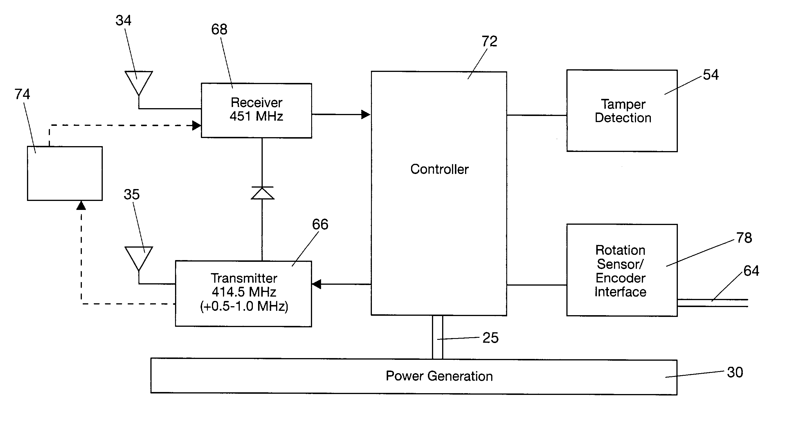
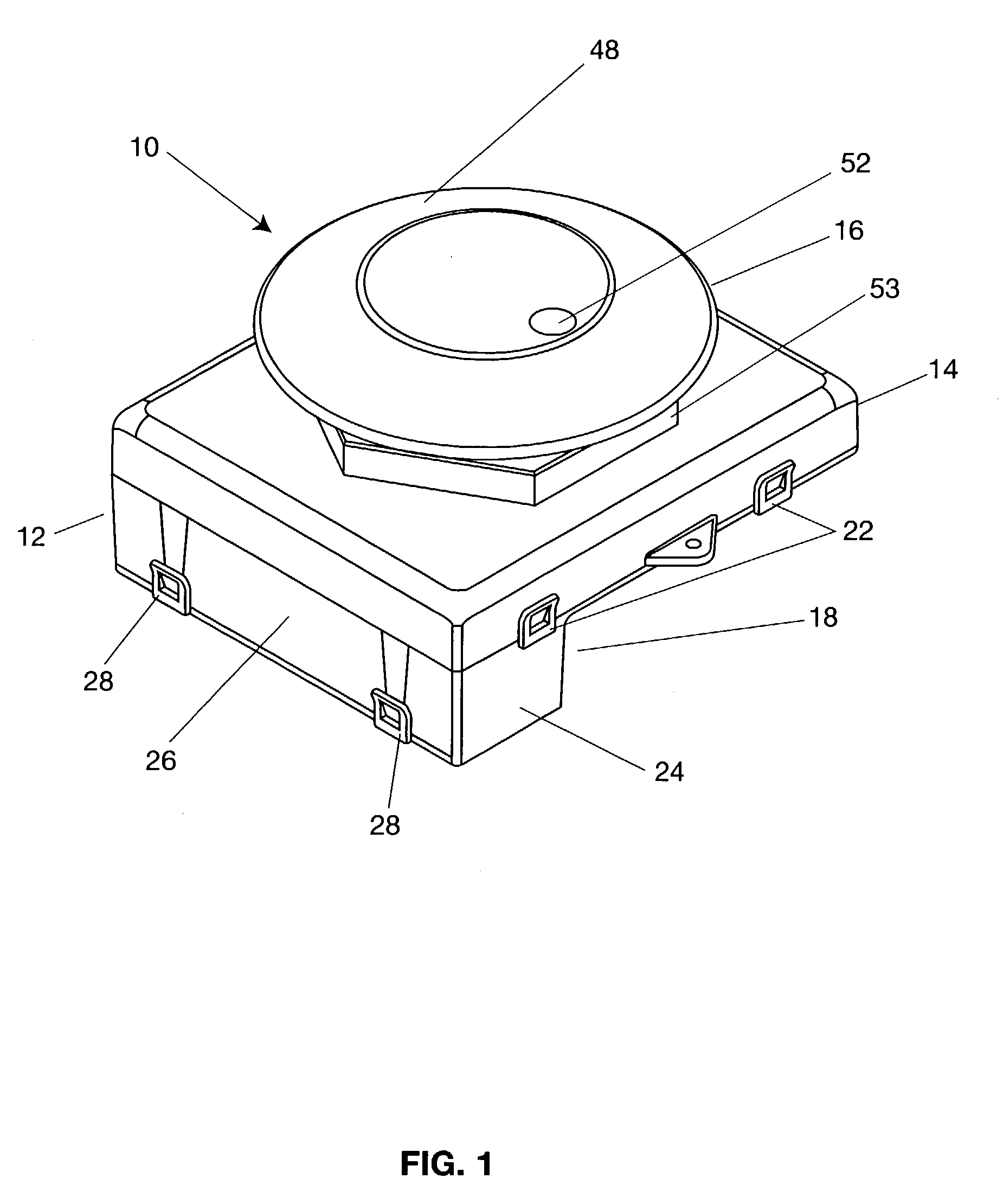
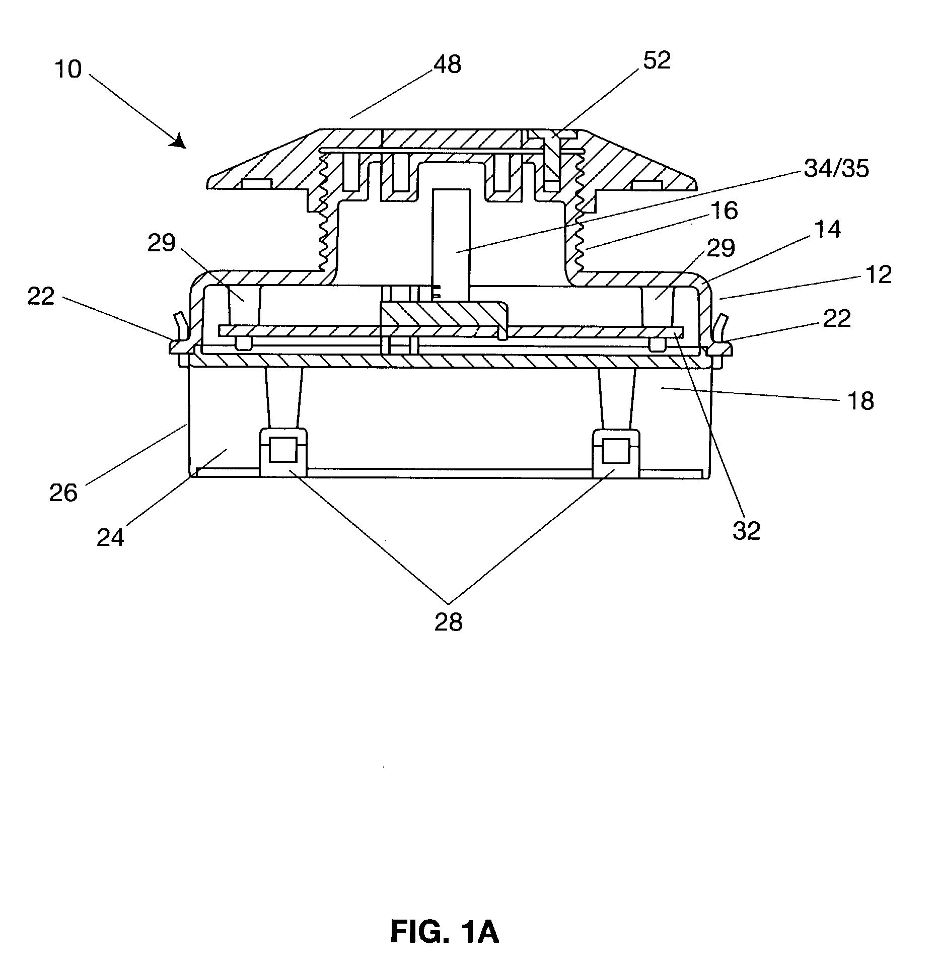
[0023]As best seen in FIGS. 1, 1A and 2, the water pit transmitter assembly 10 includes a housing 12 with multiple sections. The housing 12 is made of plastic and includes the main section 14, a top section 16 and a bottom section 18. The top section 16 is preferably configured as a cylindrical stalk of a size and shape to fit within a round hole, as is typically found on water pit lids. The top section houses the antennas, the main section houses the main electronics circuit board and the bottom section 18 houses the batteries for the unit.

[0024]The bottom faces of the main and bottom sections are fastened to the remainders of those sections with snap latches 22 and 28. The snap latc...


PUM


Abstract

A water pit transponder assembly includes a housing with multiple sections including top, main and bottom sections snap latched together connected to a water meter. A circuit board transponder in the housing includes a controller, a transmitter, a receiver and tamper detection software connected to antennas. An encoder is connected to the water meter, and batteries provide power to operate the assembly. The transponder sends and receives at different frequencies through different antennas and is protected from environmental corrosion by being encapsulated in a get inside the housing.

Description

BACKGROUND OF THE INVENTION[0001]This invention relates to an assembly attached to a water meter capable of receiving meter readings, encoding them, and transmitting the encoded meter readings to a remote mobile location.[0002]In moderate climate zones, water meters are located in underground enclosures in areas adjacent to residences, businesses or other dwellings. These enclosures are referred to as “pits” and frequently have pit lids that cover the enclosure and the water meter within the enclosure. In the last decade or so, there have been various attempts to read such meters remotely, via RF communications.[0003]Previous attempts to make devices of this type required elaborate design to ensure that the assembly is sealed against environmental conditions in its operating environment. The resulting devices are somewhat bulky and cumbersome to install and operate. In addition, previous assemblies were subject to tampering, giving false readings or disabling the device. Many of the...

Claims


Application Information

Patent Timeline
Patent Type & Authority Patents(United States)
IPC IPC(8): G08B1/00G08B1/08G01D4/00H04Q9/00
CPCG01D4/002H04Q9/00Y02B90/241Y04S20/32H04Q2209/40H04Q2209/883H04Q2209/60Y02B90/20Y04S20/30
Inventor KISER, ERICMURRAY, STEVESHUTTS, BRUCE
Owner AMCO AUTOMATED SYST
Why Eureka
Try Eureka