Proximate sensor using micro impulse waves for monitoring the status of an object, and monitoring system employing the same

a technology of proximity sensor and proximity sensor, which is applied in the direction of electrical signalling details, instruments, burglar alarm mechanical actuation, etc., can solve the problems of not being able to detect the penetration of the wall of the container, unable to provide high security against terrorists, and prone to unlawful manipulation

Inactive Publication Date: 2005-10-11
ORMON CORP
View PDF18 Cites 22 Cited by
  • Summary
  • Abstract
  • Description
  • Claims
  • Application Information

AI Technical Summary

Benefits of technology

[0011]The second objective of the present invention is to provide proximity sensors which can monitor the entire wall surface of the object under surveillance and detect any unauthorized penetration of its walls, and to provide a status surveillance system employing said sensors. Particularly, the present invention enables the detection of movement by objects emitting no heat, the detection of object movement throughout a broad space using but few sensors, and further, the provision of motion detection sensors not subject to false operation due to heat or light.
[0012]The third objective of the present invention is to provide proximity sensors which, when a plurality of sensors are installed to detect objects within a broad space, experience no interference among the electronic waves emitted from the plurality of sensors, to thereby provide a smoothly working system by means of shifting the transmission time of the electronic waves from the sensors to assure that the transmissions of one do not affect the others.
[0014]To achieve the foregoing objectives, the present invention adds proximity sensor functions to wireless communication nodes inside of the object of surveillance, such as inside of a container. Said proximity sensors output microimpulse waves from the wireless communication nodes, and said communication nodes receive the reflections of those waves from nearby objects. The wave reception sampling is performed based upon the bit signals of the clock for the microimpulse transmissions and the local clock, and the analysis of the received signals enables the highly precise measurement of the distance to an object using simple circuitry. It is then possible to detect an abnormal occurrence inside the object of surveillance by comparing the characteristic data obtained from the initial environment with that data obtained during the period of surveillance. Further, the proximity sensing function is able to detect the direction of any penetration.
[0016]To wit, the principle of the present invention, as shown in FIG. 1, involves the mounting of a plurality of communication nodes with transmitting antennas on a container's inside walls, and which transmit a microimpulse wave at a specific strength, and that output microimpulse wave reflects off of the penetration object 2, and is received by the receiving antennas 3 to comprise the proximity sensor PS. The change is then detected in reflected wave RW between the waveform from the pre-penetration RW-1 to the post-penetration RW-2. In other words, the frequency component of the reflected wave RW is affected by the velocity of the penetrating object, and further, since the physical properties of the penetrating object affect the amplitude component, the post-analysis of the reflected wave RW makes it possible detect the state of the object under surveillance, for example, the inside of a container.
[0017]The present invention further provides for the measurement of the distances between all of the desired number of communication nodes, and those distances are recorded in advance. Then, should a suspicious object penetrate or be taken from the container during its transport, the propagation state of the microimpulse waves inside the container would change, and that change can be detected. The prerecording of the distance between the various communication nodes can be used as a type of fingerprint information, and by detecting any change in that fingerprint thereafter, it is possible to detect whether a suspicious object has been secreted into the container or whether any of the cargo has been taken out.
[0018]Further, the present invention can configure the proximity sensors PS with respect to the container walls so that there are outputs of two layers, top and bottom of the microimpulse waves. Accordingly, should a suspicious article be secreted through the wall surface, it is possible to detect which of the two layered detection area detected it first, and whether the penetration was from outside to inside or vice versa, inside to outside.

Problems solved by technology

The installation conditions for such conventional types of wall sensors was fixed, and accordingly they were unable to provide high levels of security against terrorists or the like.
Further, when such sensors were not used in a stationary place such as a room, but rather inside a container or other such mobile object, at a place far removed from the security administrator, they were even more prone to unlawful manipulation.
However, with this sort of object motion detection apparatus, it would not always be possible to detect the penetration of a wall of a container, for example, that held both the transmitter means 1 and receiver means 3.
Such a system would also be easily affected by the cargo inside the container.
Further, reflection of the electronic waves by a suspicious article incoming at a dead angle would not allow adequate detection of the suspicious article.
Further, inasmuch as such conventional motion detectors, in their detection of unauthorized penetration, are applied in fixed positions inside the object of surveillance such as a container, their data could be easily but unlawfully manipulated by an inside worker on behalf of a terrorist, etc.
Further still, inasmuch as such conventional motion detectors, in their detection of unauthorized penetration, are unable to discern the position or the direction of the unauthorized penetration, they cannot produce detailed data on the unauthorized penetration such as at what velocity the penetration was made, and accordingly, even if they could detect the fact of an unauthorized penetration, they could not be used as the basis for a response thereafter.
Additionally, in object penetration detection systems of the prior art that employed a plurality of sensors using impulse waves, the output impulse waves from the sensors tended to interfere with each other making them difficult to function as detection systems.

Method used


Image

  • Proximate sensor using micro impulse waves for monitoring the status of an object, and monitoring system employing the same
  • Proximate sensor using micro impulse waves for monitoring the status of an object, and monitoring system employing the same
  • Proximate sensor using micro impulse waves for monitoring the status of an object, and monitoring system employing the same

Examples


first embodiment

Proximity Sensing (First Embodiment)

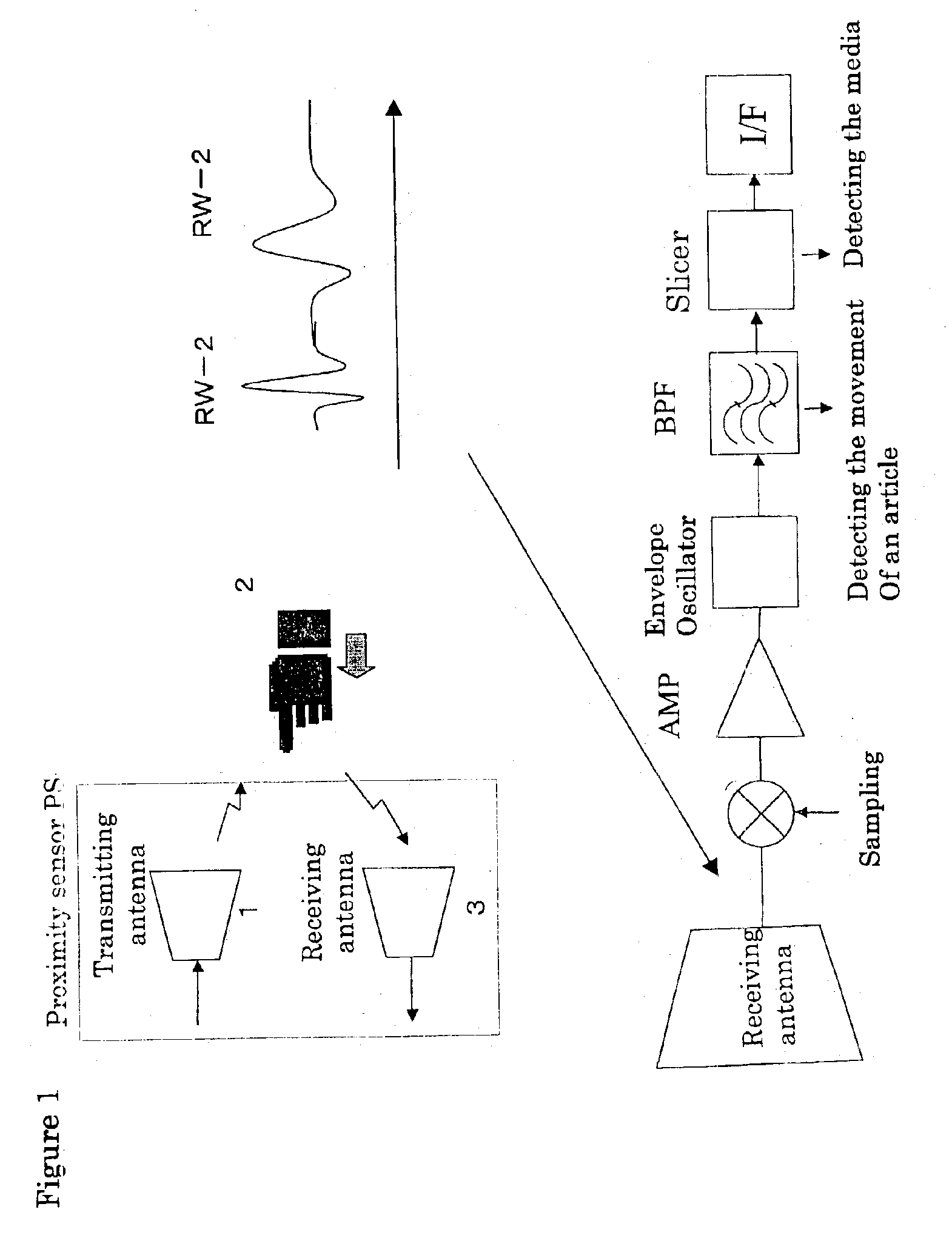
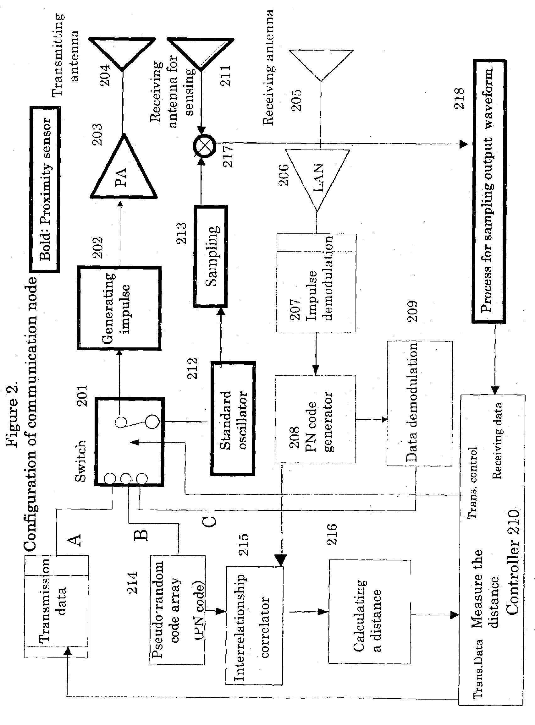
[0044]Thus, in the data communications mode, the communication nodes 2 inside the object of surveillance, the container, share a variety of basic data relating to the data communication nodes, and then, the proximity sensing according to the present invention is implemented in the numerical order of the wireless communication nodes, or in some other specific order. What is meant by proximity sensing is that each of the communication nodes output a microimpulse wave, which when reflected off the objects situated inside the container (the transport cargo), allows data regarding the distance between the objects and the proximity sensors, the strength of the reflections, and in the case of movement, the speed of that movement to be detected. More specifically, the object of surveillance, the inside of the container, is thereby guaranteed to be in a safe state. For example, if a regular shipping worker loads the container and then, prior to its being s...

second embodiment

Proximity Sensing (Second Embodiment)

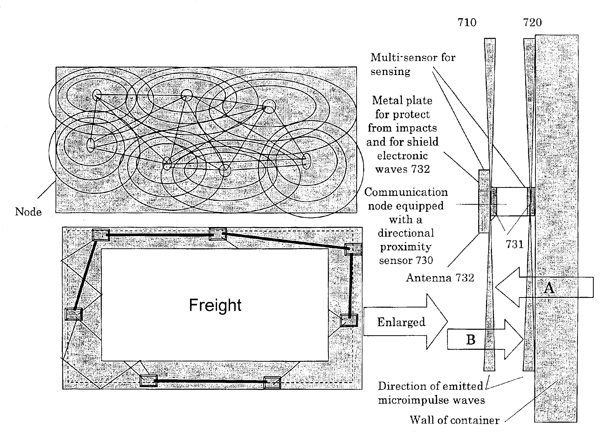
[0049]The second embodiment of proximity sensing according to this invention differs from the first embodiment's proximity sensor, which output three dimensional microimpulse waves from a transmitting antenna. As shown in FIG. 7, the proximity sensors output a plurality of film like layers that run approximately parallel to the inner walls of the container. More precisely, each communication node 730 is equipped with a directional proximity sensor having a plurality of slots 731 (in this example, two slots) of a specific width. The structure is such that microimpulse waves 710 and 720 emitted through these two slots 731 are output in a direction that is parallel to the side wall of the container. A metal plate 732 having the required properties is installed on the side facing the inside of the container over each of the directional proximity sensor-equipped communication nodes 730 in order to protect them from impacts and to shield their electron...


PUM


Abstract

The objective of the present invention is to provide proximity sensors employing impulse waves to detect the characteristics of objects lying inside the object of surveillance, such as a container, including their distance, the reflection strength from an object, the speed an object is moving, etc., as well as to provide a status surveillance system which detects, from the data from the proximity sensors, that the inside of the container remains unchanged. To achieve the foregoing objectives, the present invention adds proximity sensor functions to wireless communication nodes inside of the object of surveillance, such as inside of a container. Said proximity sensors output microimpulse waves from the wireless communication nodes, and said communication nodes receive the reflections of those waves from nearby objects. The wave reception sampling is performed based upon the bit signals of the clock for the microimpulse transmissions and the local clock, and the analysis of the received signals enables the highly precise measurement of the distance to an object using simple circuitry. It is then possible to detect an abnormal occurrence inside the object of surveillance by comparing the characteristic data obtained from the initial environment with that data obtained during the period of surveillance. Further, the proximity sensing function is able to detect the direction of any penetration.

Description

[0001]These are now pending as patent applications: U.S. patent application filed Feb. 25, 2002 (application Ser. No.: 10 / 080,927), U.S. patent application filed Apr. 10, 2002 (application Ser. No.: 10 / 119,310), and U.S. patent application filed Jul.23, 2002 (application Ser. No.: 10 / 200,552).FIELD OF TECHNOLOGY OF THE INVENTION[0002]The present invention relates to a status surveillance system and to the proximity sensors it employs, which either monitor the space proximate to the object of surveillance (e.g. inside of warehouse, containers, vehicles, office or dwelling rooms, our the area outside of a garage) by using microimpulse waves transmitted by a plurality of communication nodes positioned on inside walls, and the detection of those reflections off the objects stored inside the space, or by using proximity sensors to monitor an object of surveillance to detect the presence or absence of an unauthorized penetration by a dangerous article through its walls. The invention furt...

Claims


Application Information

Patent Timeline
Patent Type & Authority Patents(United States)
IPC IPC(8): G08B25/00G08B13/181G08B13/18G08B13/24
CPCG08B13/181G08B13/24G08B13/2462G08B13/2491G08B25/009
Inventor NAKAMURA, AKIHIKOHISANO, ATSUSHI
Owner ORMON CORP
Why Eureka
Try Eureka