Antenna device for transmitting and/or receiving radio frequency waves and method related thereto

a radio frequency wave and antenna technology, applied in the direction of diversity/multi-antenna systems, substation equipment, polarisation/directional diversity, etc., can solve the problem that the antenna cannot be later on adapted to any specific, and achieve the effect of convenient control, convenient installation and reliable, and convenient manufactur

Inactive Publication Date: 2005-10-11
SAMSUNG ELECTRONICS CO LTD
View PDF37 Cites 42 Cited by
  • Summary
  • Abstract
  • Description
  • Claims
  • Application Information

AI Technical Summary

Benefits of technology

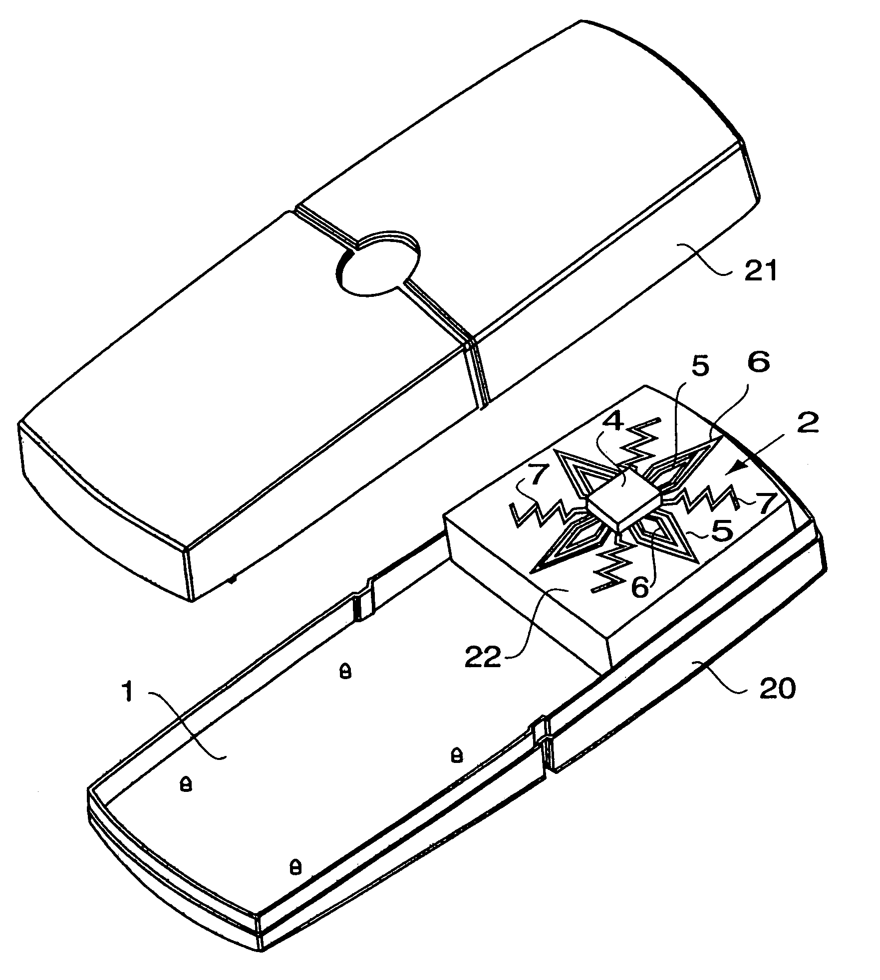
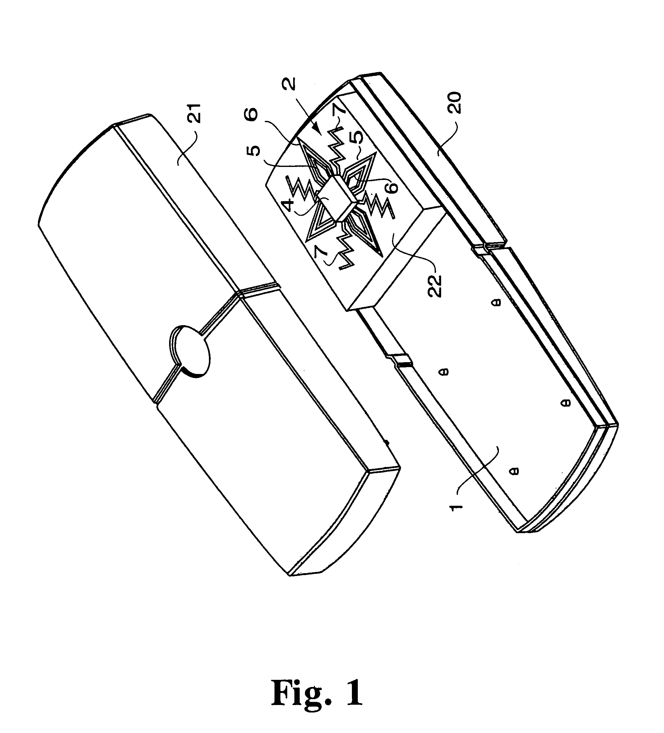
[0008]It is an object of the present invention is to provide a versatile antenna device, adaptable to various conditions, for a communication device. In this respect, it is a particular object of the invention to provide a versatile antenna device, which is adaptable to its close-by environment.
[0009]It is yet a further object of the invention to provide an antenna device of which certain characteristics, such as resonance frequency, input impedance bandwidth, radiation pattern, gain, is polarization, and near-field pattern, are easily controllable.
[0010]It is still a further object to provide an antenna device that is simple, lightweight, easy to manufacture and inexpensive.
[0011]It is yet a further object to provide an antenna device which is efficient, easy to install and reliable, particularly mechanically durable, even after long use.

Problems solved by technology

It is thus a formidable task to manufacture such compact and versatile terminals, which exhibit good antenna performance under a variety of conditions.
This means that the antenna cannot later on be adapted to any specific condition under which a certain telephone is to be used.

Method used


Image

  • Antenna device for transmitting and/or receiving radio frequency waves and method related thereto
  • Antenna device for transmitting and/or receiving radio frequency waves and method related thereto
  • Antenna device for transmitting and/or receiving radio frequency waves and method related thereto

Examples


Embodiment Construction

[0018]In the following description, for purposes of explanation and not limitation, specific details are set fourth in order to provide a thorough understanding of the present invention. However, it will be apparent to one skilled in the art that the present invention may be practiced in other embodiments that depart from these specific details. In other instances, detailed descriptions of well-known devices and methods are omitted so as not to obscure the description of the present invention with unnecessary details.

[0019]In this disclosure it is to be understood that the antenna system of the invention is operable to transmit or receive electromagnetic signals. Even if a term is used herein that suggests one specific signal direction it is to be appreciated that such a situation can cover that signal direction and / or its reverse. The expression “antenna structure” is intended to include active elements connected to the transmission (feed) line(s) of the communication device circui...


PUM


Abstract

An antenna device for transmitting and/or receiving electromagnetic radiation, installable in and connectable to a communication device, inlcudes an antenna structure switchable between a plurality of antenna configuration states. Each antenna configuration state is distinguished by a set of radiation parameters, such as resonance frequency, input impedance, bandwidth, radiation pattern, gain, polarization, and near-field pattern. Each of the plurality of antenna configuration states is adapted for use of the antenna device in the communication device in a respective predefined physical operation environment. A switching device selectively switches the antenna structure between the plurality of antenna configuration states.

Description

CROSS REFERENCE TO RELATED APPLICATIONS[0001]The present invention claims priority to commonly assigned Swedish Patent Application Serial No. 9903945-5 filed Oct. 29, 1999 and is a continuation of PCT Patent Application Serial No. PCT / SE00 / 02059 filed on Oct. 24, 2000, the entire contents of all of which are hereby incorporated by reference in their entirety for all purposes. The present application is also related to commonly assigned, co-pending U.S. patent application Ser. No. 09 / 712,131 entitled “An antenna device for transmitting and / or receiving RF waves”, now U.S. Pat. No. 6,392,610; U.S. patent application Ser. No. 09 / 712,181 entitled “Antenna device and method for transmitting and receiving radio waves”; and U.S. patent application Ser. No. 09 / 712,133 entitled “Antenna device and method for transmitting and receiving radio frequency waves”, all of which were filed concurrently herewith. These applications are based on the following corresponding PCT applications: PCT / SE00 / 0...

Claims


Application Information

Patent Timeline
Patent Type & Authority Patents(United States)
IPC IPC(8): H01Q1/36H01Q3/24H01Q1/24
CPCH01Q1/242H01Q1/36H01Q3/247H04B7/02
Inventor BRAUN, CHRISTIANEDVARDSSON, OLOVERIKSSON, LEIF
Owner SAMSUNG ELECTRONICS CO LTD
Why Eureka
Try Eureka