Conformal retro-modulator optical devices

a retro-modulator and optical device technology, applied in the direction of reradiation control devices, instruments, etc., can solve the problems of limiting the ability to retrofit existing large, curved surfaces, and dramatic limitations in the depth of modulation (optical contrast ratio) described in the prior art, and achieve high bandwidth, high efficiency, and high bandwidth communication

Inactive Publication Date: 2005-10-11
HRL LAB
View PDF16 Cites 14 Cited by
  • Summary
  • Abstract
  • Description
  • Claims
  • Application Information

AI Technical Summary

Benefits of technology

[0028]In yet another aspect of this invention, Asymmetric Fabry-Perot (AFP) MQW structures are utilized as the pixellated elements. The AFP structures can perform dual functions: they can act an optical modulator (low-voltage, high-depth-of-modulation and bandwidth) and as an optical detector (high efficiency, high bandwidth). Finally, refractive, reflective, and / or diffractive optical elements (in transmission or reflection modes) can be employed to complete the specific device structure. The result is a low-cost, rugged, conformal, and robust retro-modulation device with large field-of-view and large field-of-regard, capable of high-bandwidth communication and IFF (identification, friend or foe) applications, with Low Probability of Intercept / Detection (LPI / LPD).

Problems solved by technology

In addition, the depth-of-modulation (optical contrast ratio) described in the prior art are dramatically limited by the finite thickness of the thin MQW modulator (typically, 1 μm total thickness).
This would normally limit the ability to retrofit existing large, curved surfaces with a large-area MRR device of such a construction.
Moreover, the field-of-view may be limited by such a planar structure, even in the case of a large-area device.
In addition, the prior art does not describe how to use a dual-mode device for the MRR structure (for both photodetection and optical modulation).
Also, the prior art does not disclose how to fabricate a device with Low Probability of Intercept / Detection (LPI / LPD) in a common element, so that the retro-reflected beam is disabled prior to a successful handshaking procedure (the prior art requires a stand-alone optical shutter to prevent a third party from interrogating the MRR).
Finally, the prior art does not disclose a simple method of how to enable the MRR to deal with multiple wavelength indication.
Utilizing a stand-alone shutter to prevent undesirable interrogation of the MRR (as would be the case in the prior art) has a disadvantage since it does not allow the prior art devices to function as a detector and a retro-modulator.

Method used


Image

  • Conformal retro-modulator optical devices
  • Conformal retro-modulator optical devices
  • Conformal retro-modulator optical devices

Examples


Embodiment Construction

A Conformal Modulated-Retro-Reflective Optical Device

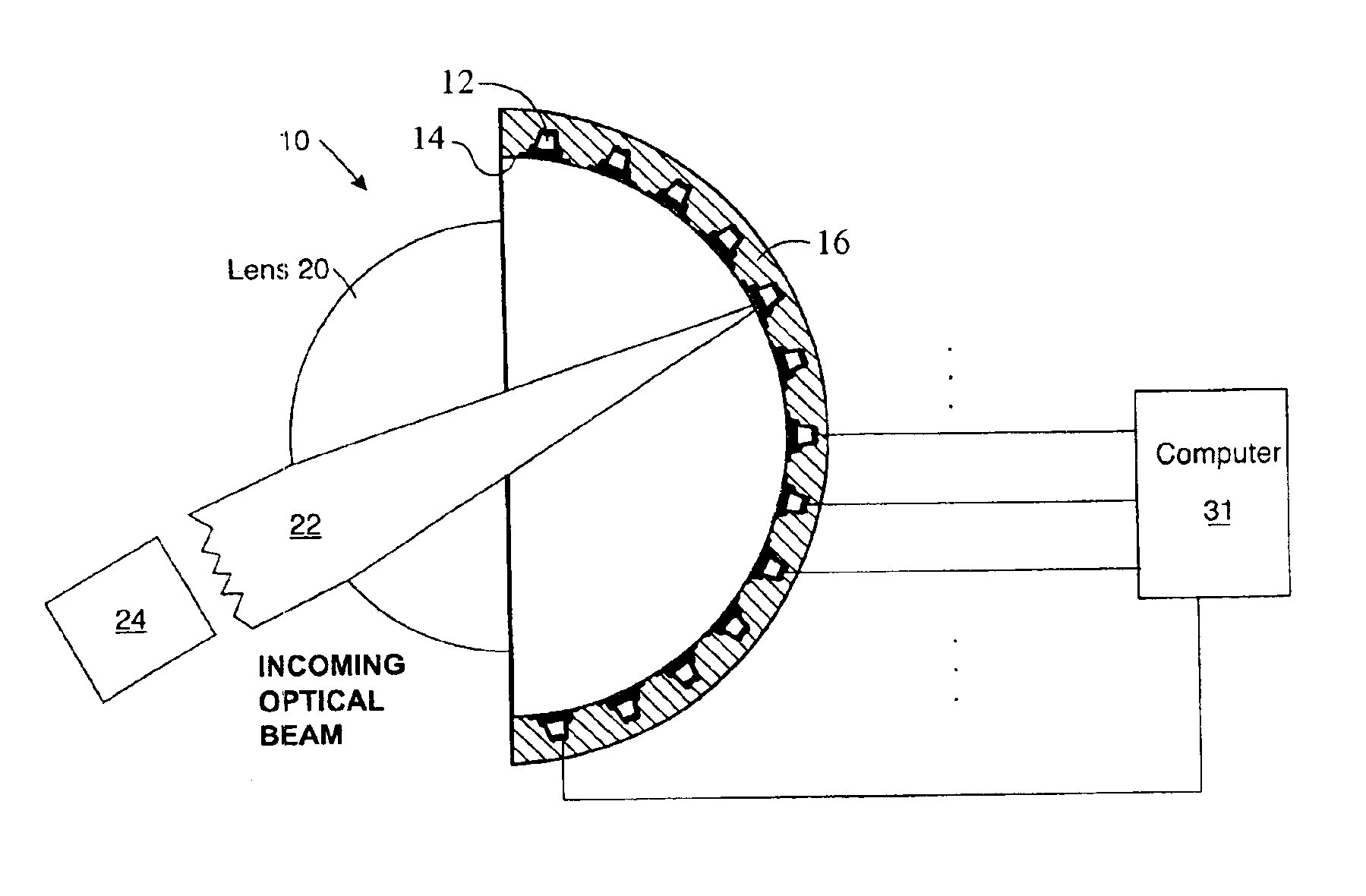
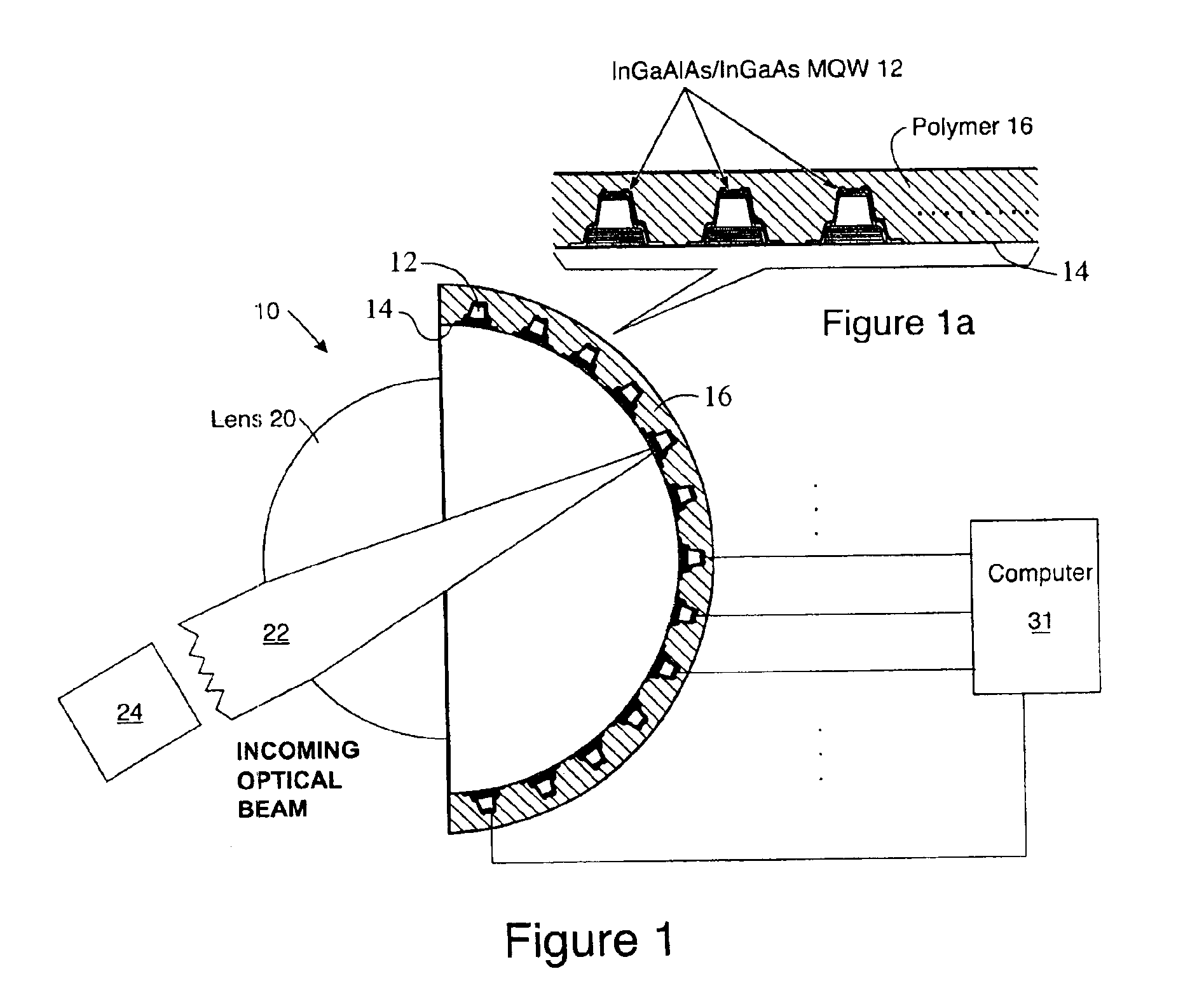
[0044]FIG. 1 is sectional view through an embodiment of a conformal retro-modulator reflective optical device 10. The device 10 has an array of modulator / detector pixels 12 disposed along a surface 14. An optical arrangement 20 (such as a lens) focuses an incoming optical beam 22 on one or more of the pixels 12 in the array. In this embodiment, the surface 14 conforms to a hemispherical shape. As will be seen, the surface 14 may be of any desired shape, including planar, but the optical arrangement 20 does need to be able to deliver incoming light 22 to selected pixels 12. In FIG. 1 the optical arrangement 20 is depicted as a single lens and a single lens can often suitably focus the beam on a geometric surface like the hemispherical surface 14 shown in FIG. 1. Other optical arrangements 20 may be utilized, including Fresnel lenses, holographic “lenses”, diffractive optical gratings, computer-controlled phase plates, multiple lens...


PUM


Abstract

A conformal retro-modulator optical apparatus. The apparatus includes an array of multiple quantum well devices disposed in a thin array. A plastic support element is bonded to the thin array, the plastic support element having a thickness greater that of the thin array. The plastic support element is preferably plastic at elevated temperatures above room temperature, thereby allowing the plastic support element and the thin array of multiple well device disposed therein to conform to a predetermined shape, yet being rigid at room temperature.

Description

CROSS REFERENCE TO RELATED APPLICATION[0001]This application is related to and claims the benefits of U.S. Provisional Patent Application No. 60 / 420,177, filed Oct. 21, 2002, the disclosure of which is hereby incorporated herein by this reference. The subject matter of the present application may also be related to the following U.S. patent application: “Optical Retro-Reflective Apparatus” Ser. No. 10 / 661,028, filed Sep. 11, 2003.BACKGROUND[0002]1. Field[0003]The present invention relates to new classes of pixellated and conformal Modulated-Retro-Reflective (MRR) optical devices, including modulated corner-cube devices as well as modulated cat's eye devices. Instead of using a single, large-area modulator, the disclosed modulator utilizes an array of individual pixels, which can be independently controlled or modulated. The array need not be planar and can be formed to any shape as required by the optical design of the specific device structure.[0004]2. Description of Related Art[00...

Claims


Application Information

Patent Timeline
Patent Type & Authority Patents(United States)
IPC IPC(8): G01S17/74G01S17/00G02B5/12H01L27/146H04B10/10H04B10/26
CPCG01S17/74G02B5/12H01L21/6835H01L27/14647H04B10/112H04B10/2587H01L2924/1461H01L24/18H01L24/82H01L24/96H01L2221/6835H01L2224/24051H01L2224/24226H01L2924/01078H01L2924/30105H01L2924/3511H01L2924/00H01L2924/12042H01L2924/12043
Inventor SAYYAH, KEYVANPEPPER, DAVID M.BREWER, PETER D.AU, ANSON
Owner HRL LAB
Why Eureka
Try Eureka