Method of generating control data for bending and torsion apparatuses

a technology of bending and torsion and control data, which is applied in the direction of program control, total factory control, instruments, etc., can solve the problems of not being able to contribute to the manufacture of a product of the dimensional accuracy within the permissible range required, unable to eliminate dimensional deviations or errors in a manufactured product, and unable to completely reflect the longitudinal axis of a bent elongated workpiece. to achieve the effect of reliable effect of bending and higher

Inactive Publication Date: 2005-10-11
HONDA MOTOR CO LTD
View PDF13 Cites 27 Cited by
  • Summary
  • Abstract
  • Description
  • Claims
  • Application Information

AI Technical Summary

Benefits of technology

[0011]It is accordingly an object of the present invention to provide a method of generating a control data, capable of allowing a bending apparatus to reliably effect bending on an elongated workpiece at a higher accuracy.

Problems solved by technology

However, it is the fact that a straight line cannot completely reflect the longitudinal axis of a bent elongated workpiece.
The definition for the positions of the movable die according to the aforementioned plane of the three-dimensional coordinate system consequently cannot contribute to manufacture of a product of the dimensional accuracy within a permissible range required for a practical use.
In general, a simple calculation for deriving the positions of the movable die, based on a shape data specifying an image of a designed product within a coordinate system, cannot eliminate dimensional deviations or errors in a manufactured product.
These factors inevitably induce difficulty to specify the quantity of the corrections or compensations.
Operators should suffer from a troublesome collection of measurement results.
However, the feed speed of the straight elongated workpiece cannot easily be specified based on an image of a bent product in the three-dimensional coordinate system.
For example, the shapes or designs for industrial products, such as automobiles and electric household appliances, cannot be determined without considering methods of manufacture or mass production.
Heretofore, no one proposes a bending machine capable of effecting torsion on an elongated workpiece as expected.

Method used


Image

  • Method of generating control data for bending and torsion apparatuses
  • Method of generating control data for bending and torsion apparatuses
  • Method of generating control data for bending and torsion apparatuses

Examples


Embodiment Construction

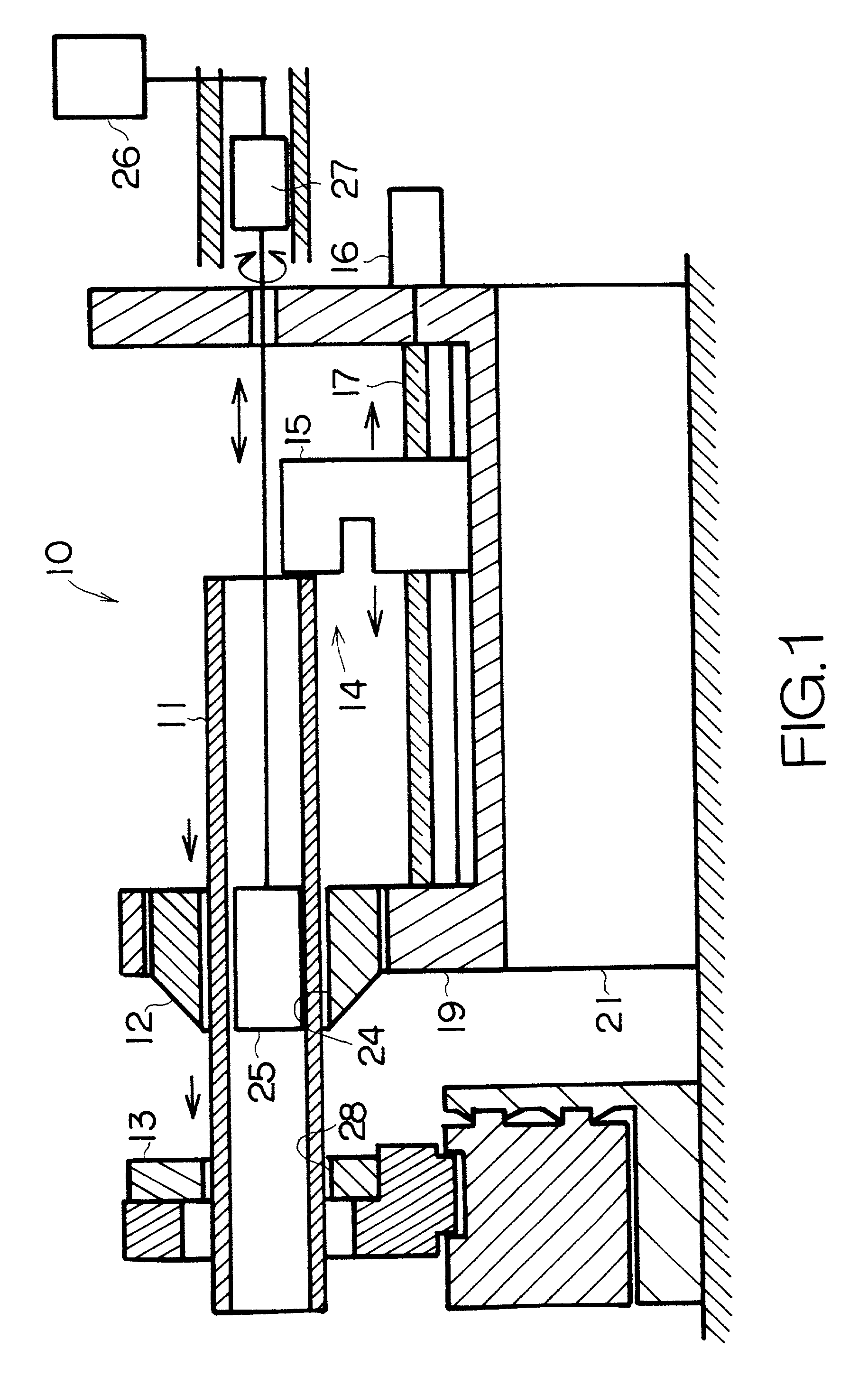
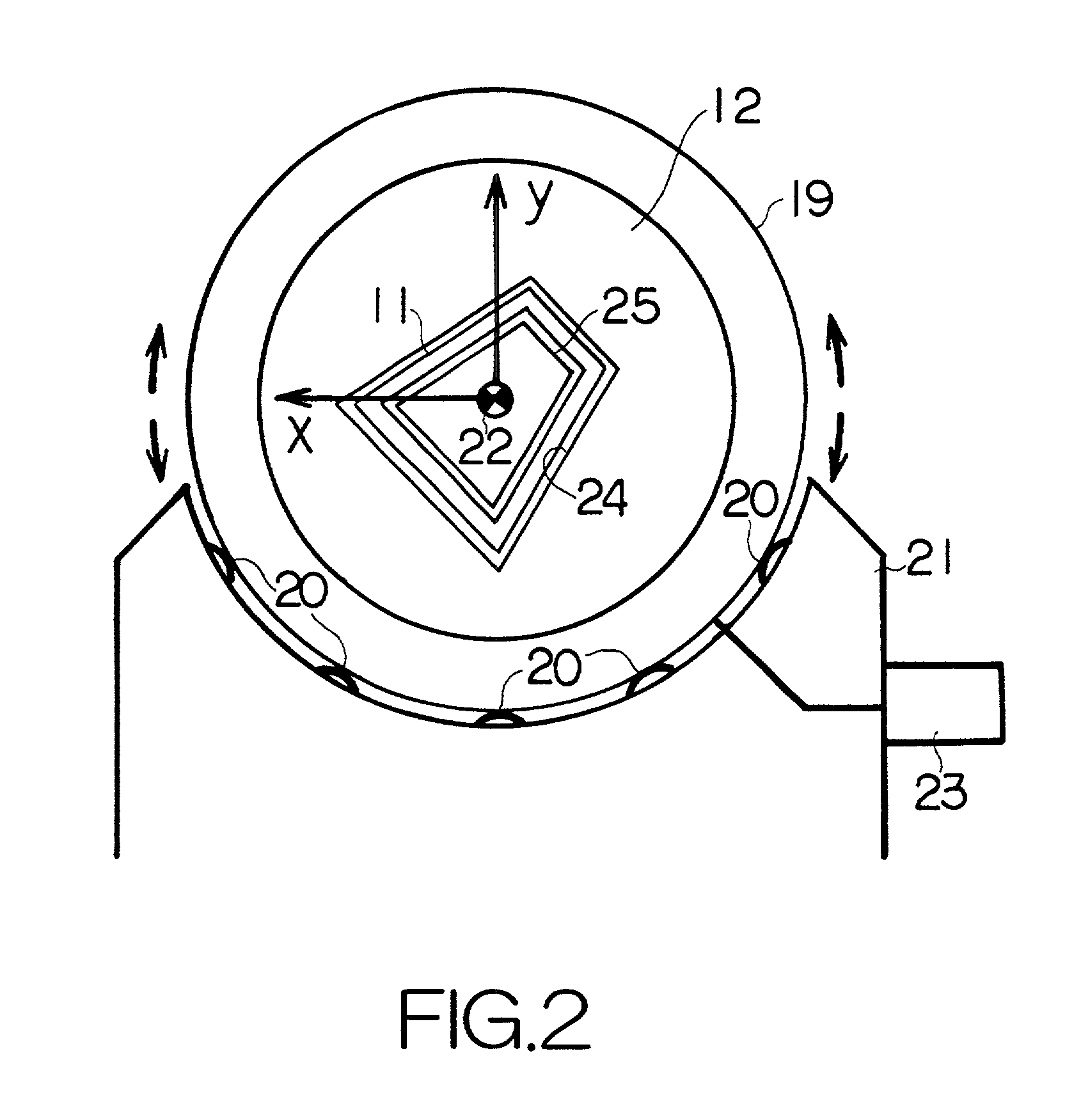
[0140]FIG. 1 schematically illustrates the structure of a bending apparatus or machine 10. The bending machine 10 includes a first or rear stable die 12 and a second or front movable die 13 designed to guide the advancement of an elongated workpiece 11 in combination with the stable die 12, and a feeder mechanism 14 designed to feed the elongated workpiece 11 to the stable and movable dies 12, 13. The bending machine 10 allows the movable die 13 to move or shift within a plane perpendicular to the direction of the advancement of the elongated workpiece 11, as described later in detail. The movement of the movable die 13 serves to effect bending on the elongated workpiece 11.

[0141]The feeder mechanism 14 includes a slider 15 designed to contact the rear end of the elongated workpiece 11, and a push rod or threaded rod 17 converting the rotation of a feed motor 16 to the advancement or driving force of the slider 15. A ball screw mechanism may be established between the threaded rod 1...


PUM

PropertyMeasurementUnit
shapeaaaaaaaaaa
bending momentaaaaaaaaaa
plasticaaaaaaaaaa

Abstract

A shape data specifies the shape of an elongated product within an overall coordinate system. Local coordinate systems are defined on respective cross-sections of the elongated product in the overall coordinate system. The local coordinate system is designed to represent a stable die of a bending apparatus. The images of the elongated product protruding forward from the stable die within the respective local coordinate systems serve to specify the position of a movable die of the bending apparatus. The specified position reflects the deformation induced in the elongated product between the stable and movable dies. An ideal movement amount of the movable die can be determined based on the determined positions within the local coordinate systems. The determined movement amount can be utilized to prepare the control data for the bending apparatus. When the prepared control data is supplied to the bending apparatus, an ideal movement of the movable die can be achieved so as to effect bending on the elongated workpiece at a higher accuracy in accordance with the shape data.

Description

BACKGROUND OF THE INVENTION[0001]1. Field of the Invention[0002]The present invention relates to a bending apparatus or machine employed to bend an elongated workpiece passing through stable and movable dies, one after the other, which movable die is allowed to move or shift relative to the stable die so as to bend the elongated workpiece.[0003]The term “curve” may optionally include a line comprising nodes and arcs connecting the adjacent nodes in the following description.[0004]2. Description of the Prior Art[0005]A software program such as a numerical control (NC) program can be employed to control the operation of any types of machine tools, including a bending machine. The software program must specify control data such as data defining a displacement or shift amount of a movable die in the bending machine, for example. Heretofore, skilled operators or workers are in general forced to write down the control data based on their intuition and experience. The written control data ...

Claims


Application Information

Patent Timeline
Patent Type & Authority Patents(United States)
IPC IPC(8): B21D7/00B21D7/12G05B19/4097
CPCB21D7/12G05B19/4097G05B2219/35192G05B2219/36203G05B2219/45143Y02P90/02
Inventor TAKEDA, KENZOMARUYAMA, MANABUMEGURI, HIDEOKAGEYAMA, YOSHIHIRO
Owner HONDA MOTOR CO LTD
Why Eureka
Try Eureka