Cavitation detection in a process plant

a technology of cavitation detection and process control, which is applied in the direction of ratio control, mechanical power/torque control, and fluid pressure measurement by mechanical elements. it can solve the problems of little if any flow of information from one functional area of the plant, and the process control operator (either a human or a software expert) does not have the benefit of this information

Inactive Publication Date: 2005-10-11
FISHER-ROSEMOUNT SYST INC
View PDF142 Cites 46 Cited by
  • Summary
  • Abstract
  • Description
  • Claims
  • Application Information

AI Technical Summary

Benefits of technology

[0012]A process control system may use an asset utilization expert to collect data or information pertaining to the assets of a process plant from various sources or functional areas of the plant including, for example, the process control functional areas, the maintenance functional areas and the business systems functional areas and uses this information to detect and possibly take corrective actions. In one example, a monitoring system is configured to detect or predict cavitations within equipment, such as pumps, within a plant. In this example, process variable or operational parameter data, such as measured flow rates and pressures, may be combined with maintenance data, such as characteristic curves, to detect or predict cavitation within a pump or other device. Similarly, process data and pump manufacturing data may be combined with process or device models to detect the existence of or likely formation of cavitation within a device.

Problems solved by technology

In the past however, process controllers were not necessarily aware of these other devices or the process controllers simply assumed that these devices were operating properly when performing process control.
Such optimizers typically use complex models of the plant to predict how inputs may be changed to optimize operation of the plant with respect to some desired optimization variable such as, for example, profit.
Furthermore, even if all of the applications are located within a plant, because different personnel use these different applications and analysis tools and because these tools are generally located at different hardware locations within the plant, there is little if any flow of information from one functional area of the plant to another, even when this information may be useful to other functions within the plant.
This tool may detect a problem and alert the maintenance person that the device needs to be calibrated, repaired or replaced.
However, the process control operator (either a human or a software expert) does not have the benefit of this information, even though the poorly operating device may be causing a problem that is affecting a loop or some other component which is being monitored by the process control operation.
Likewise, the business person is not aware of this fact, even though the malfunctioning device may be critical to and may be preventing optimization of the plant in a manner that the business person may desire.
Because the process control expert is unaware of a device problem which may be ultimately causing poor performance of a loop or unit in the process control system and because the process control operator or expert assumes that this equipment is operating perfectly, the process control expert may misdiagnose the problem it detects within the process control loop or may try to apply a tool, such as a loop tuner, which could never actually correct the problem.
Likewise, the business person may make a business decision to run the plant in a manner that will not achieve the desired business effects (such as optimizing profits) because of the malfunctioning device.
However, in the past, because these functions were separated, the information generated or collected in one functional area was not used at all, or not used very well in other functional areas which led to an overall sub-optimal use of the assets within process plants.

Method used


Image

  • Cavitation detection in a process plant
  • Cavitation detection in a process plant
  • Cavitation detection in a process plant

Examples


Embodiment Construction

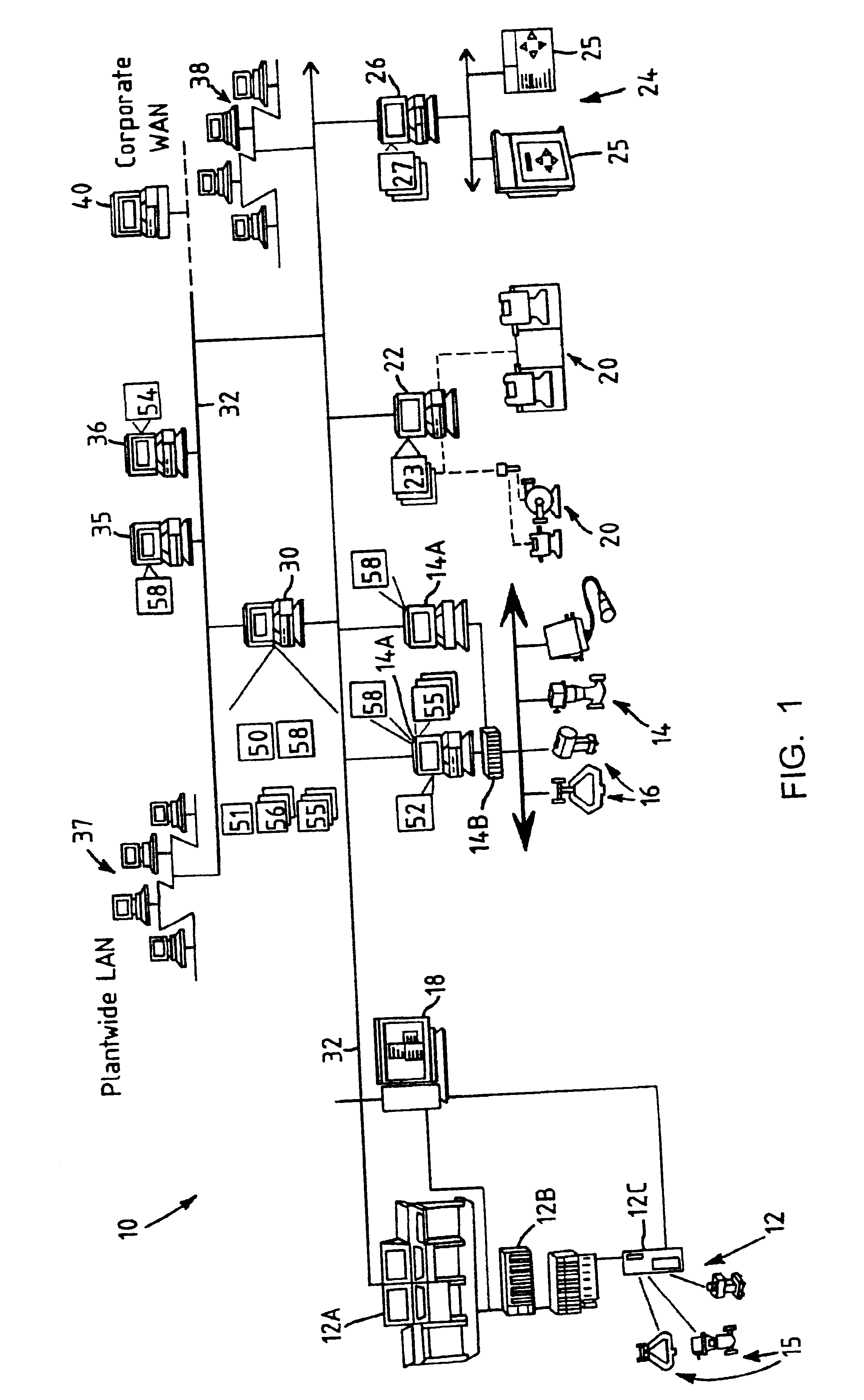
[0022]Referring now to FIG. 1, a process control plant 10 includes a number of business and other computer systems interconnected with a number of control and maintenance systems by one or more communication networks. The process control plant 10 includes one or more process control systems 12 and 14. The process control system 12 may be a traditional process control system such as a PROVOX or RS3 system or any other DCS which includes an operator interface 12A coupled to a controller 12B and to input / output (I / O) cards 12C which, in turn, are coupled to various field devices such as analog and Highway Addressable Remote Transmitter (HART) field devices 15. The process control system 14, which may be a distributed process control system, includes one or more operator interfaces 14A coupled to one or more distributed controllers 14B via a bus, such as an Ethernet bus. The controllers 14B may be, for example, DeltaV™ controllers sold by Fisher-Rosemount Systems, Inc. of Austin, Tex. o...


PUM

PropertyMeasurementUnit
suction pressureaaaaaaaaaa
voltage-current characteristicaaaaaaaaaa
voltage-current characteristic curveaaaaaaaaaa

Abstract

A monitoring system for use in a process plant having a pump or other device capable of undergoing cavitation, uses a characteristic curve, a model and/or process variables, such as indications of a flow rate within the device or a pressure at the input of the device, to detect or predict the occurrence of cavitation within the device. Upon detecting the occurrence of cavitation, the monitoring system may alert a user to the existence of the cavitation, may suggest possible causes of the cavitation and may suggest possible actions to be taken to alleviate the cavitation.

Description

RELATED APPLICATION[0001]This is a regularly filed application based on and claiming priority from Provisional Application 60 / 273,164, filed Mar. 1, 2001 entitled “Asset Utilization Expert in a Process Control Plant.”FIELD OF THE INVENTION[0002]The present invention relates generally to process control systems within process plants and, more particularly, to the use of a coordinated monitoring system to aid in the detection of cavitation in a process control plant.DESCRIPTION OF THE RELATED ART[0003]Process control systems, like those used in chemical, petroleum or other processes, typically include one or more centralized or decentralized process controllers communicatively coupled to at least one host or operator workstation and to one or more process control and instrumentation devices, such as field devices, via analog, digital or combined analog / digital buses. Field devices, which may be, for example valves, valve positioners, switches, transmitters, and sensors (e.g., temperat...

Claims


Application Information

Patent Timeline
Patent Type & Authority Patents(United States)
IPC IPC(8): G05B23/02
CPCG05B23/0243
Inventor ERYUREK, EVREN
Owner FISHER-ROSEMOUNT SYST INC
Why Eureka
Try Eureka