Pyrospin combuster

a combustible and pyrospin technology, which is applied in the direction of combustion process, hot gas positive displacement engine plant, lighting and heating apparatus, etc., can solve the problems of reducing the efficiency of fuel and air mixing, preventing the flow of air through reducing the efficiency of swirling effect provided by the film cooling holes, so as to facilitate efficient cooling of the combustor liner, enhance the annular circumferential swirling of fuel, and improve the effect of fuel mixing

Inactive Publication Date: 2005-10-18
HAMILTON SUNDSTRAND CORP
View PDF8 Cites 80 Cited by
  • Summary
  • Abstract
  • Description
  • Claims
  • Application Information

AI Technical Summary

Benefits of technology

[0004]The invention comprises an annular combustor with radial fuel injection, referred to as a “Pyrospin Combustor”, that has angled effusion holes through at least one surface of the combustor liner with the angle of the effusion holes oriented to enhance annular circumferential swirling of the fuel and air and the fire spinning within the combustor. The effusion holes thereby facilitate efficient cooling of the combustor liner combined with superior fuel and air mixing and enhanced fire spinning within the combustor.

Problems solved by technology

Although these cooling strips are effective in facilitating good fuel and air mixing and enhancing fire spinning within the combustor, the efficiency of the swirling effect provided by the flow of the air through the film cooling holes is prohibited by the strips.
This is because the strips cause cooling air momentum loss, thereby reducing efficient mixing of the fuel and air.

Method used


Image

  • Pyrospin combuster
  • Pyrospin combuster
  • Pyrospin combuster

Examples


Embodiment Construction

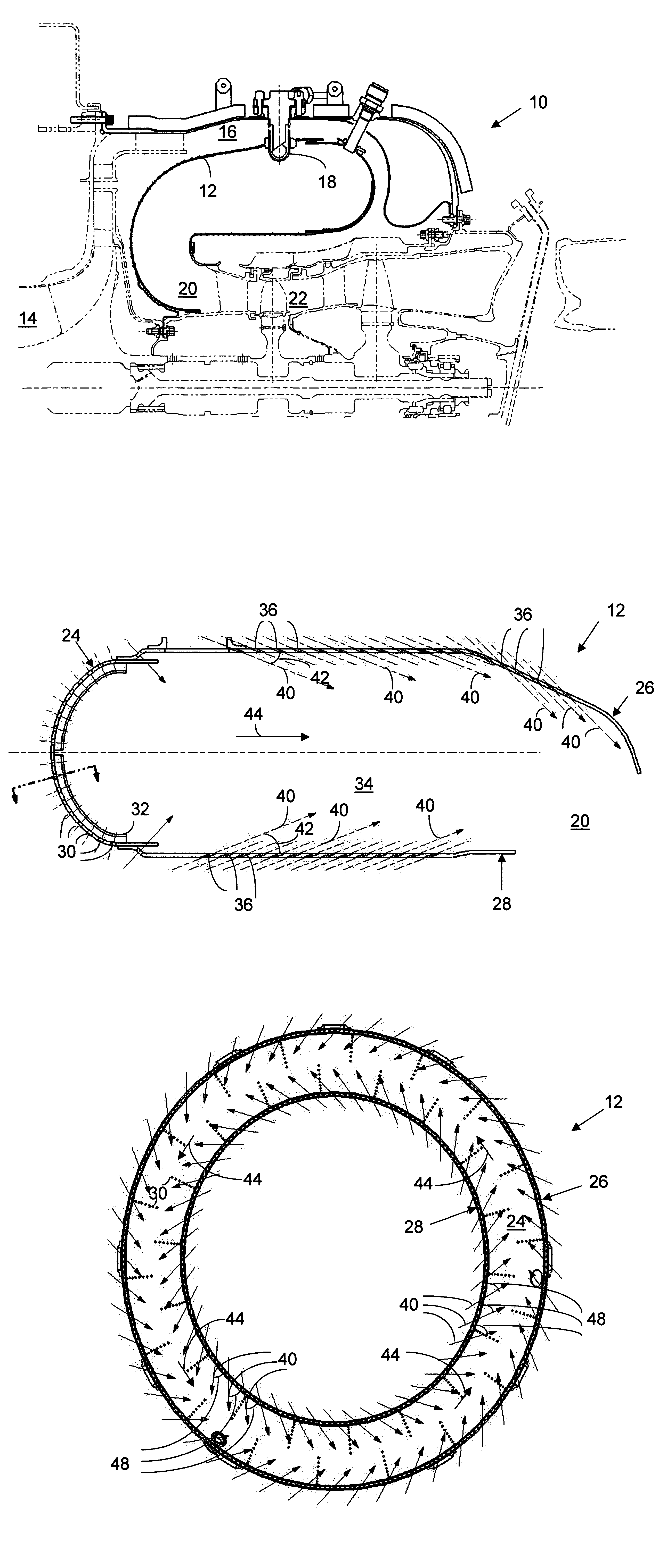
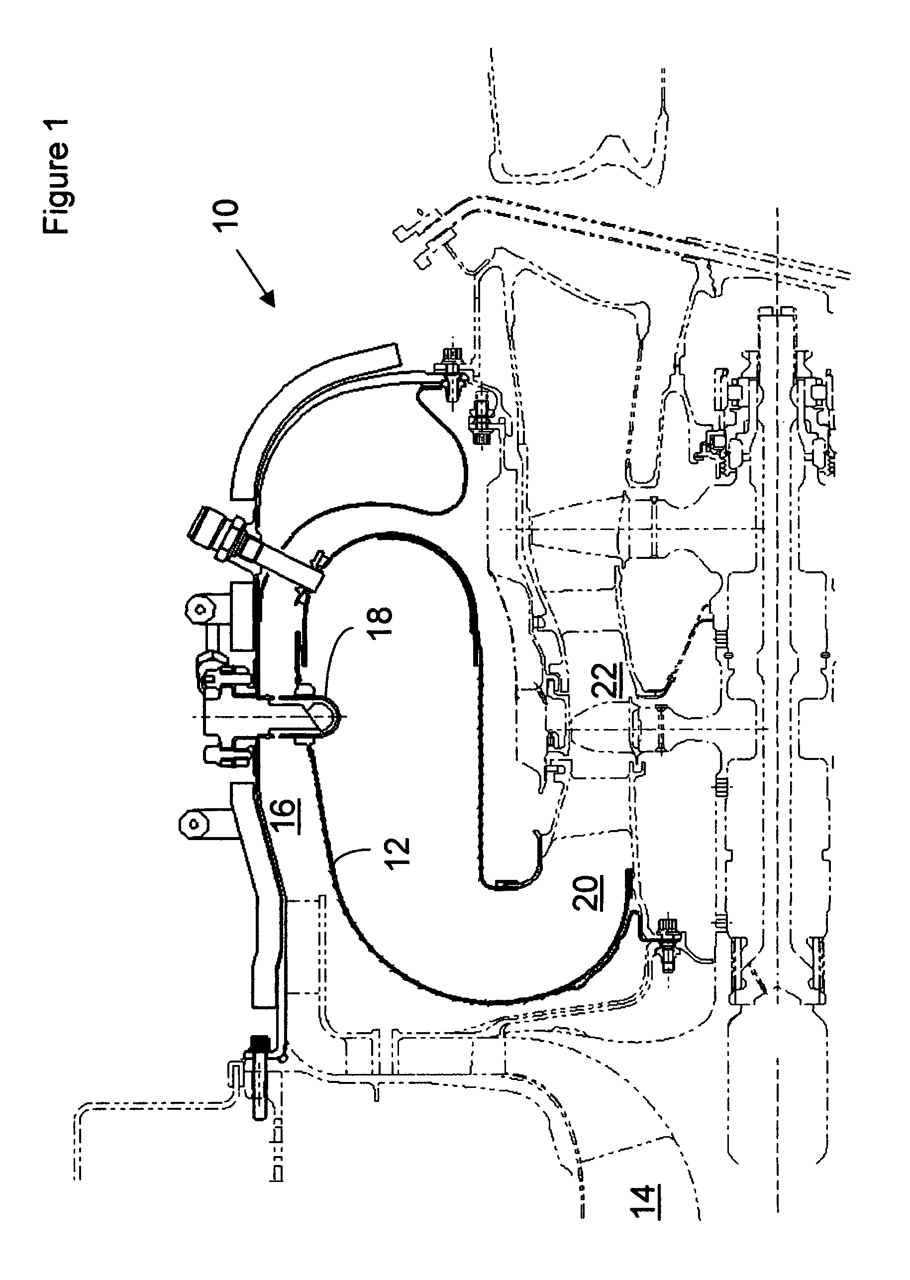
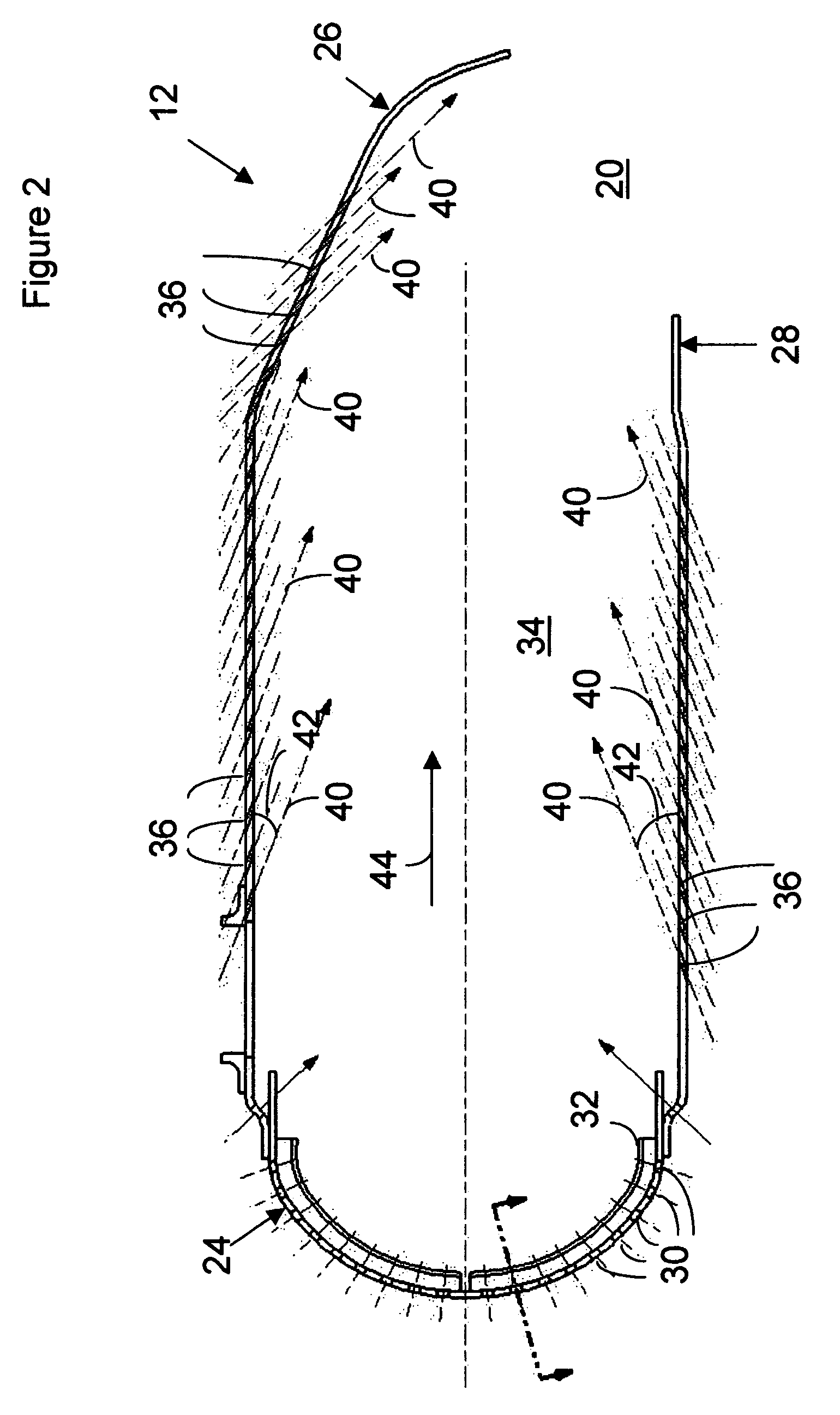
[0016]Referring to the drawings, wherein numbered items describe like or corresponding parts throughout the views, FIG. 1 is a fragmentary sectional view of a gas turbine 10 that incorporates the invention. The turbine 10 comprises a “Pyrospin Combustor”12 that is supplied with compressed air from a compressor section 14 of the turbine 10 through a plenum region 16 that encloses the combustor 12. Compressed air in the plenum region 16 is forced through apertures (not shown) in the liner walls of the combustor 12 and mixed with fuel supplied by a plurality of fuel injectors 18 to initiate combustion. The combustion gases thereby generated are exhausted through a combustor outlet 20 to drive a turbine section 22 of the turbine 10.

[0017]The compressed air that is forced through apertures in the liner walls of the combustor 12, besides serving to oxidise the fuel to support combustion, is used to dilute the combustion gases generated in the combustor 12 and to cool the surfaces of the c...


PUM


Abstract

An annular combustor that has angled effusion holes through at least one surface of the combustor liner with the angle of the effusion holes oriented to cause the flow of air through the holes to facilitate swirling of the fuel and air within the combustor. The effusion holes thereby facilitate efficient cooling of the combustor liner combined with superior fuel / air mixing within the combustor.

Description

BACKGROUND OF THE INVENTION[0001]For a gas turbine engine that employs an annular combustor with radial fuel injection, it has long been known that achieving uniform annular circumferential swirl of fuel and air downstream of the primary combustion zone provides a much more uniform mix to provide a more uniform burn. This results in more annular circumferential uniformity in the turbine inlet temperature. It has been common to provide cooling strips along the inner and outer annular walls, as well as the dome, of the combustor to facilitate this annular circumferential swirl. Such cooling strips baffle air that flows through adjacent film cooling holes in a generally annular circumferential direction. The film cooling holes release pressurised air.[0002]Although these cooling strips are effective in facilitating good fuel and air mixing and enhancing fire spinning within the combustor, the efficiency of the swirling effect provided by the flow of the air through the film cooling hol...

Claims


Application Information

Patent Timeline
Patent Type & Authority Patents(United States)
IPC IPC(8): F23R3/54F23R3/00F23R3/06F23R3/50F23R3/58
CPCF23R3/06F23R3/50F23R3/54F23R3/58F23R2900/03041
Inventor CHEN, DAIH-YEOUHAYDEN, CHRISTREES, DIETMARPICONI, PAULREICHMANN, TONYVITALE, JACK
Owner HAMILTON SUNDSTRAND CORP
Why Eureka
Try Eureka