Eureka AIR delivers breakthrough ideas for toughest innovation challenges, trusted by R&D personnel around the world.

Caliper method, system, and apparatus

a technology of calipers and afm, applied in the field of atomic force microscopes, can solve the problems of limited edge resolution of sems, difficult calibration of such probes, and significant problems remained

Inactive Publication Date: 2005-10-18
XIDEX CORP
View PDF12 Cites 23 Cited by
  • Summary
  • Abstract
  • Description
  • Claims
  • Application Information

AI Technical Summary

Benefits of technology

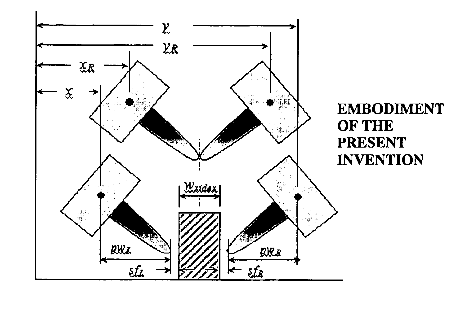
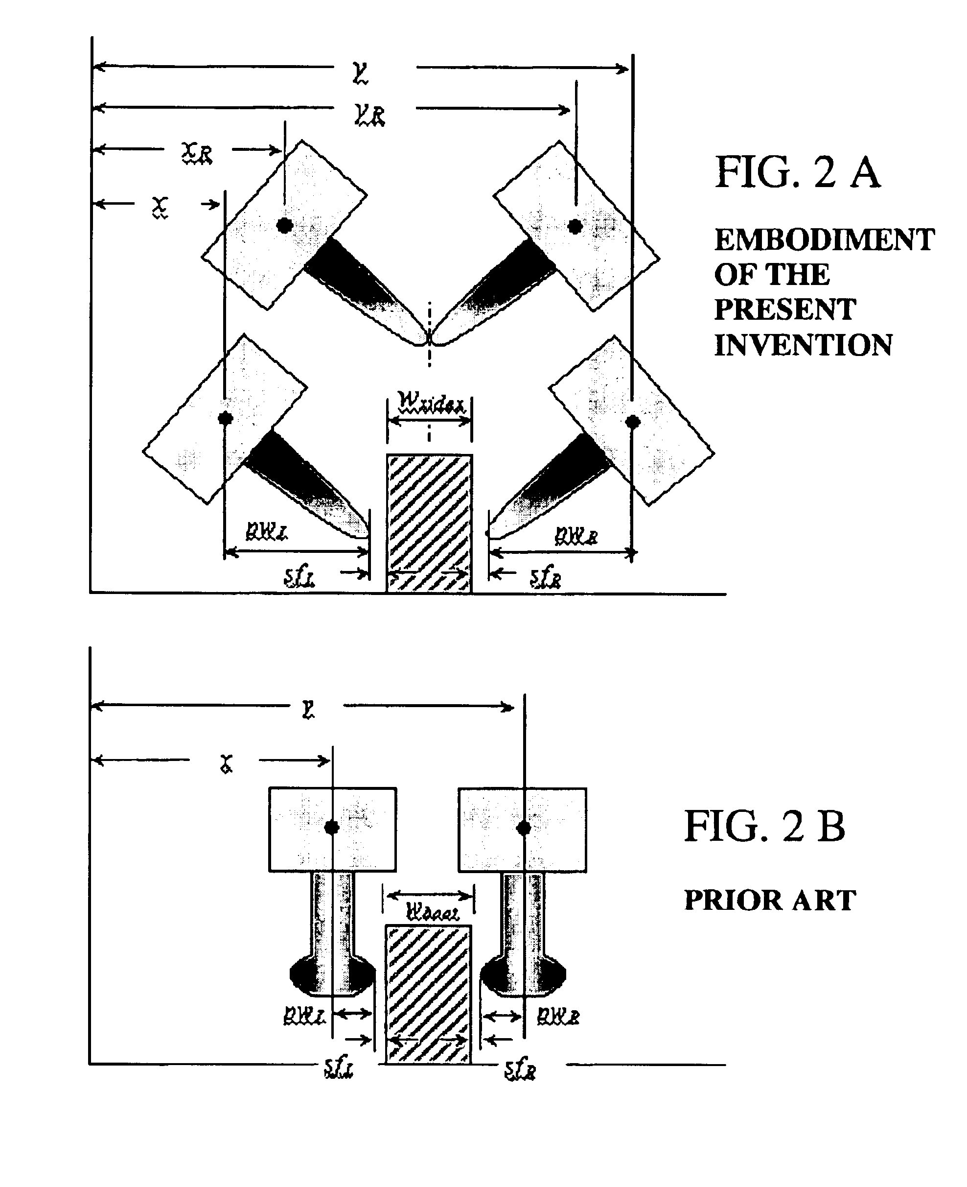
[0012]According to another embodiment of the invention, a method of test sample measurement using a caliper that has a first tip of a first AFM probe and a second tip of a second AFM probe includes positioning the first tip on a first surface of the test sample, positioning the second tip on a second surface of the test sample, creating a first data set by measuring the test sample with the first tip, and creating a second data set by measuring the test sample with the second tip and the first tip and the second tip are operably coordinated.

Problems solved by technology

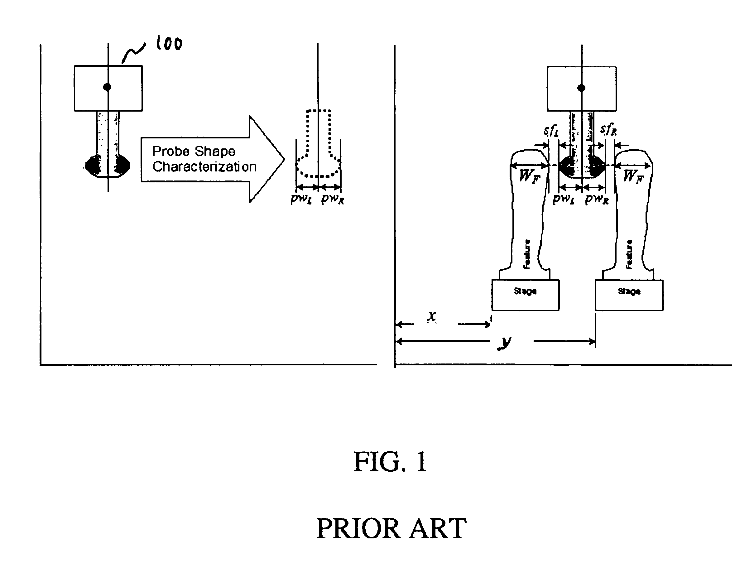
Conventional atomic force microscope (AFM) probes have been developed to perform nanometer-scale measurements on test surfaces, but while those solved many problems, significant problems remained.
For example, calibration of such probes is difficult.
However, even on thinned sections the edge resolution of SEMs is limited by the beam-sample interaction.
However, the scale calibration of TEM relies on comparison of the measured images with calibrated artifacts, such as atomic lattice spacings, under nearly identical imaging conditions and is difficult to carry out with high precision.
Furthermore, both of these techniques are destructive and involve off-line measurements in vacuum.

Method used


Image

  • Caliper method, system, and apparatus
  • Caliper method, system, and apparatus
  • Caliper method, system, and apparatus

Examples


Embodiment Construction

[0078]Throughout this description, primed reference characters correspond to unprimed reference characters. For example, reference character 1′ would correspond to the reference character 1.

The Problem Solved by the Present Invention

[0079]The main disadvantage of scanning-probe measurement tools is their dependence on a priori knowledge of the probe's shape and its interaction with the test sample to reconstruct the dimensions of the test sample from raw measurement data. In the case of a conventional atomic force microscope (AFM), great effort must be expended to characterize probe tip shape in the presence of tip wear, estimate the tip-surface force profile in the presence of surface contamination and variable material composition, and calibrate the scanning stages and other electro-optical sensors and actuators in the presence of manufacturing defects and environmental noise.

[0080]Model dependence refers to reliance on such a priori information about operation of a measurement to...


PUM


Abstract

A caliper atomic force microscope (AFM) comprises two AFM probes (each comprised of an oscillator and an attached tip) that operate on a sample in a coordinated manner. The coordinated operation of the AFM probes may be spatially or temporally coordinated. The result of the coordinated operation may be an image of the sample or a dimensional measurement of an unknown sample. The probes of the caliper AFM may be tilted, or the tips may be tilted at a non-orthogonal angle with respect to the probes, so as to enable the tips to access vertical sample surfaces or to enable the tips to touch each other. The tip shapes may include conical, boot-shaped, cylindrical, or spherical and materials from which the tips are fabricated may include silicon or carbon nanotubes. The oscillators may be beveled to allow the tips to operate in close proximity or in contact without interference of the oscillators. The disclosure of the present invention is discussed in terms of an atomic force (van der Waalls) interaction. Other interaction forces are contemplated, such as electrostatic force, magnetic force, and tunneling current. The caliper AFM may be calibrated with the help of a sample with known dimensions or by touching the probe tips. The tip-to-tip calibration enables absolute measurements without the need for a reference artifact, and it enables in-line calibration that may be performed during the measurement process.

Description

CROSS-REFERENCE TO RELATED APPLICATIONS[0001]This application claims the benefit of the following U.S. Provisional Applications, all of which are hereby incorporated by reference:[0002] COMMONLY OWNED AND PREVIOUSLY FILED U.S. PROVISIONAL PATENT APPLICATIONS Atty. Dkt. # Ser. No. Title Filing Date500929.000024 60 / 280,193 Caliper AFM for near- Mar. 30, 2001model-independentnanometrology500929.00003060 / 287,822Multiple head caliperMay 1, 2001atomic force microscope[0003]The benefit of 35 U.S.C. § 120 is claimed for all of the above referenced commonly owned applications. The contents of the applications referenced in the table above are not necessarily identical to the contents of this application.[0004]All references cited hereafter are incorporated by reference to the maximum extent allowable by law. To the extent a reference may not be fully incorporated herein, it is incorporated by reference for background purposes and indicative of the knowledge of one of ordinary ...

Claims


Application Information

Patent Timeline
IPC IPC(8): G12B21/20G12B21/08G12B21/00G01Q40/00G01Q40/02G01Q60/24G01Q60/38G01Q70/06
CPCB82Y35/00G01Q40/00G01Q40/02G01Q60/38Y10S977/874
Inventor MANCEVSKI, VLADIMIRMCCLURE, PAUL
Owner XIDEX CORP
Why Eureka
Eureka Blog
Learn More