Optical accelerometer or displacement device using a flexure system

a technology of optical accelerometer and flexure system, which is applied in the direction of force measurement by measuring optical property variation, optical radiation measurement, instruments, etc., can solve the problems of shortened device life, general reliability concerns, and the lik

Inactive Publication Date: 2005-10-18
WEATHERFORD TECH HLDG LLC
View PDF8 Cites 81 Cited by
  • Summary
  • Abstract
  • Description
  • Claims
  • Application Information

AI Technical Summary

Benefits of technology

[0009]Disclosed herein is an accelerometer and/or displacement device that uses a mass coupled to a rhomboidal flexure to provide compression to an optical sensing element preferably having a fiber Bragg grating (FBG). The transducer includes a precompressed optical sensor disposed along a first axis between sides of the flexure. The top portion of the flexure connects to the mass that intersects the flexure along a second axis perpendicular to the first axis. When the mass experiences a force due to acceleration or displacement,...

Problems solved by technology

While these prior art approaches function well to measure acceleration (dynamic forces) or displacement (constant forces), they generally require that the optical element at issue (i.e., the FBG or coil) be pretensioned, as is it ...

Method used


Image

  • Optical accelerometer or displacement device using a flexure system
  • Optical accelerometer or displacement device using a flexure system
  • Optical accelerometer or displacement device using a flexure system

Examples


Embodiment Construction

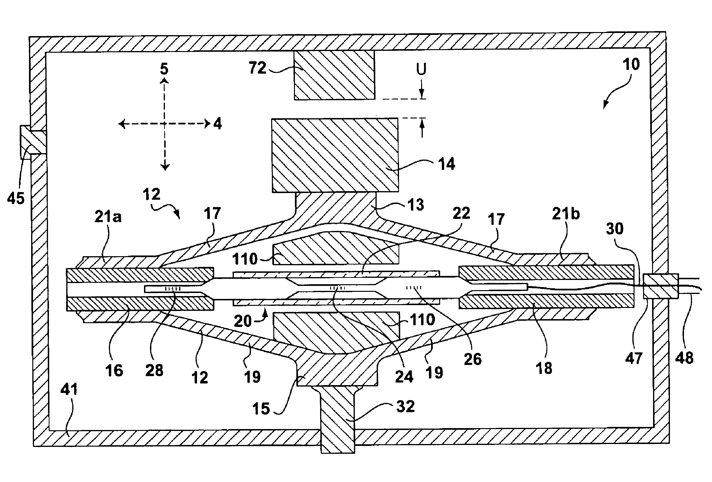
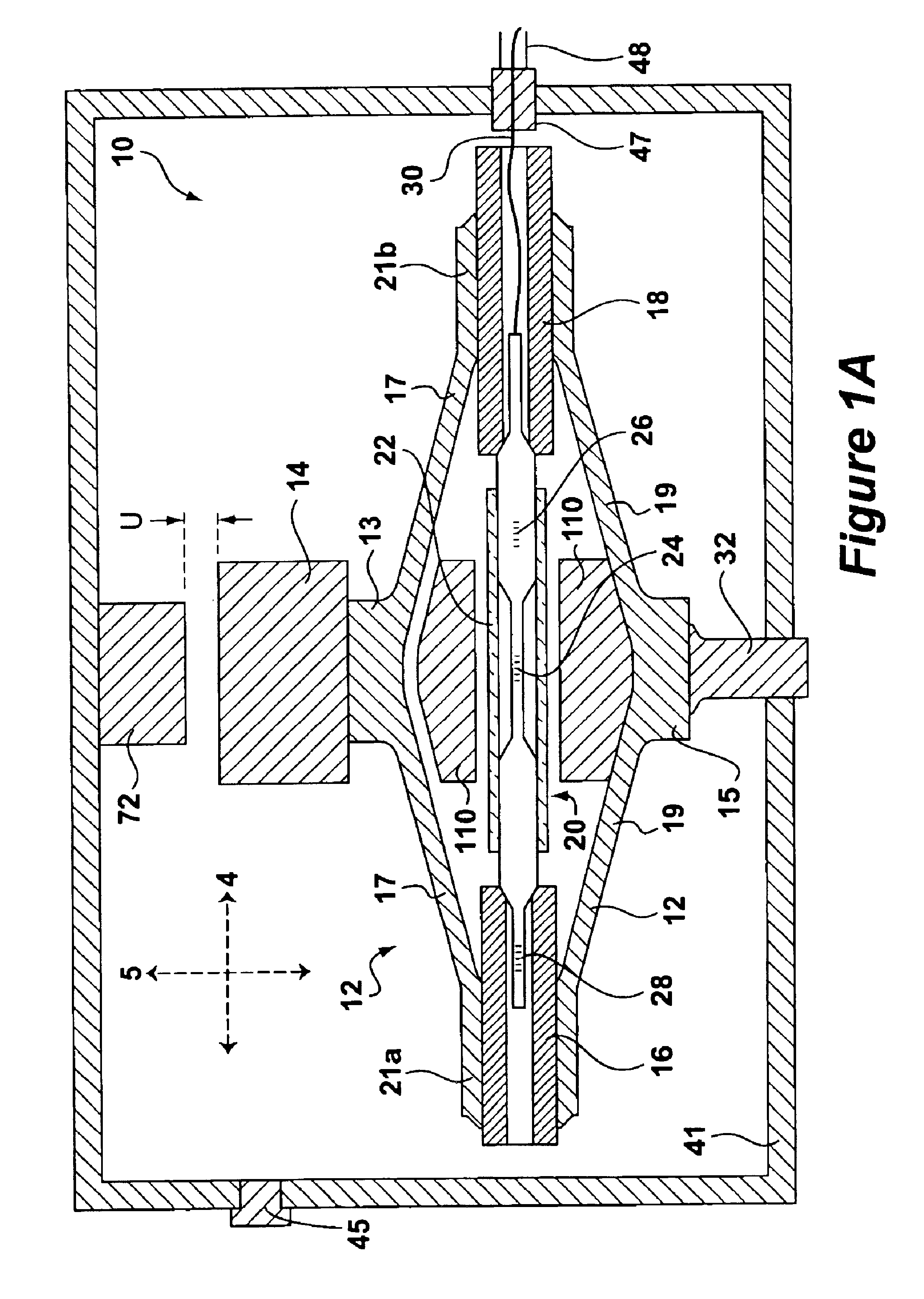
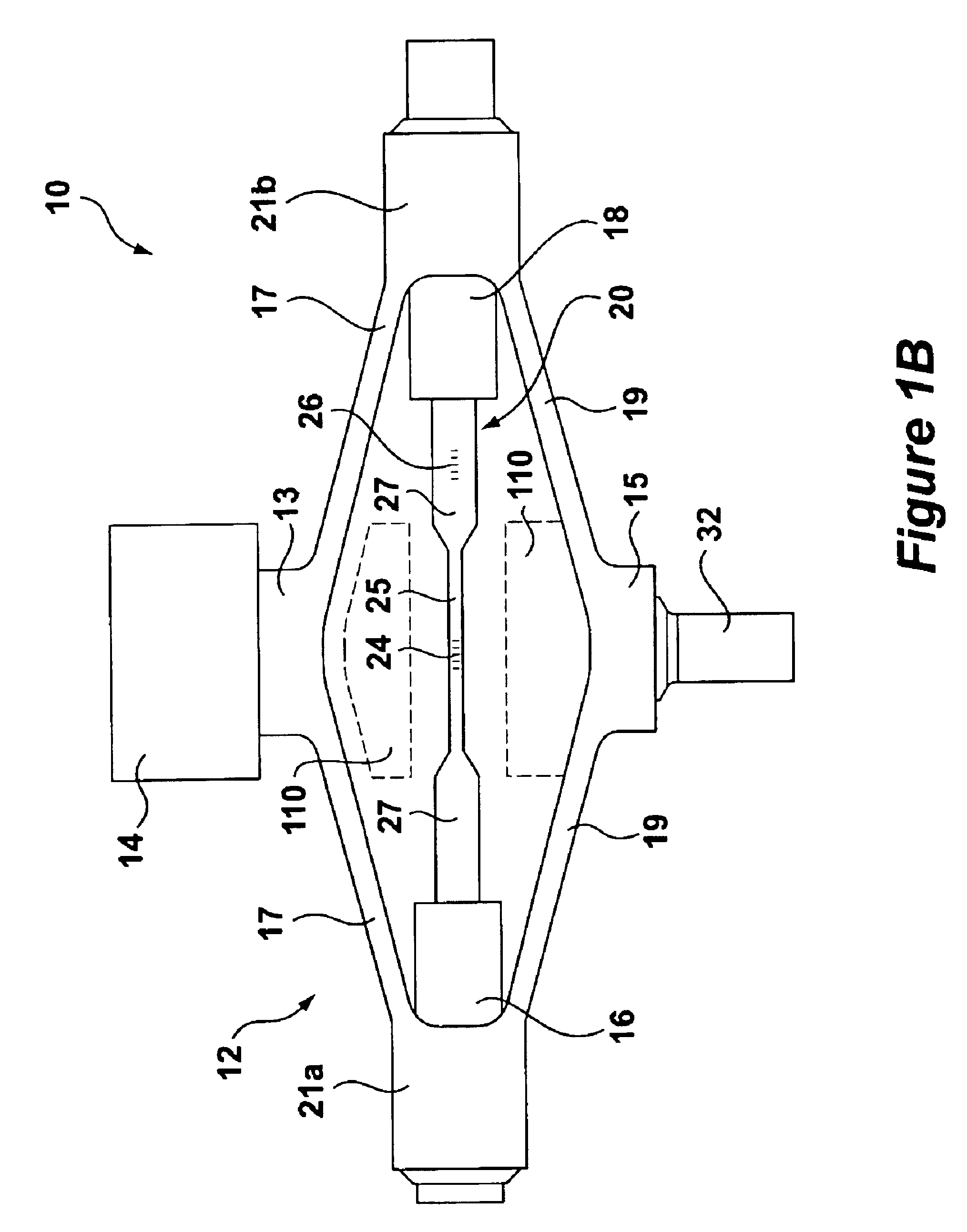
[0023]FIGS. 1A and 1B respectively disclose an accelerometer or displacement device 10 (hereinafter sensor 10) in a cross sectional and plan view. The basic components of the sensor 10 include a rhombus-shaped flexure element or spring 12, an optical sensing element 20 containing a force-sensitive FBG 24, and a mass 14. The bottom 15 of the flexure 12 is affixed to a housing 41 at securing pin 32.

[0024]In operation, a dynamic or constant force experienced along a second axis 5 will cause the mass 14 to move, which in turn causes the flexure 12 to expand or contract along the second axis 5. This in turn causes first and second end portions 21a and 21b of the flexure 12 to respectively to move towards or away from one another along first axis 4. This movement of the ends 21a and 21b will axially compress or relax the optical sensing element 20, and in particular the force-sensitive grating FBG 24, which causes the Bragg reflection wavelength of the FBG 24 to proportionately shift in a...


PUM


Abstract

Disclosed herein is an accelerometer and/or displacement device that uses a mass coupled to a rhomboidal flexure to provide compression to an optical sensing element preferably having a fiber Bragg grating (FBG). The transducer includes a precompressed optical sensor disposed along a first axis between sides of the flexure. The top portion of the flexure connects to the mass which intersects the flexure along a second axis perpendicular to the first axis. When the mass experiences a force due to acceleration or displacement, the flexure will expand or contract along the second axis, which respectively compresses or relieves the compression of the FBG in the optical sensing element along the first axis. Perturbing the force presented to the FBG changes its Bragg reflection wavelength, which is interrogated to quantify the dynamic or constant force. A temperature compensation scheme, including the use of additional fiber Bragg gratings and thermal compensators axially positioned to counteract thermal effects of the optical sensing element, is also disclosed.

Description

CROSS REFERENCES TO RELATED APPLICATIONS[0001]U.S. patent application Ser. No. 09 / 410,634, filed Oct. 1, 1999; Ser. No. 10 / 068,266, filed Feb. 6, 2002; Ser. No. 10 / 393,557, entitled “Optical Differential Pressure Transducer Utilizing a Bellows and Flexure System,” filed Mar. 21, 2003; and Ser. No. 10 / 454,101, entitled “An Optical Sensor Using A Long Period Grating Suitable for Dynamic Interrogation,” filed concurrently herewith, contain subject matter related to that disclosed herein, and are incorporated herein by reference in their entireties.TECHNICAL FIELD[0002]This invention relates to optical accelerometers or displacement devices.BACKGROUND ART[0003]Optical devices for the measurement of acceleration or displacement are known in the art. Such devices have utility in a number of different industrial applications, and specifically have utility in oil / gas applications such as seismology and well-deviation monitoring.[0004]Typically, optical accelerometers or displacement devices...

Claims


Application Information

Patent Timeline
IPC IPC(8): G01P15/08G01P15/093G01H9/00G01V1/18
CPCG01H9/004G01P15/093G01V1/184G01V1/18
Inventor JONES, RICHARD TODDMACDOUGALL, TREVOR
Owner WEATHERFORD TECH HLDG LLC
Why Eureka
Try Eureka