
Accurate cryogenic liquid dispenser

a cryogenic liquid and accurate technology, applied in the direction of liquid transferring devices, container discharge methods, instruments, etc., can solve the problems of inability to accurately measure, limited '838 patents, and inability to determine the density of lng with a high degree of accuracy

Inactive Publication Date: 2005-10-18
CHART INC
View PDF7 Cites 7 Cited by
  • Summary
  • Abstract
  • Description
  • Claims
  • Application Information

AI Technical Summary

Benefits of technology

[0018]In a further embodiment of the system, a compensating meter is substituted for the capacitor. The resulting two meters have different equations for relating mass flow to density. As a result, the equations

Problems solved by technology

A key issue in the commercialization of LNG is the ability to accurately meter and dispense it.
'838 patent is limited, however, due to the fact that LNG is made up of many chemical components.
As a result, the density of LNG cannot be determined with a high degree of accuracy simply by the conventional temperature correlations, which are based upon an approximation of the LNG composition.
Such an arrangement, however, presents stability issues in that the signals provided to the microprocessor by the pressure sensors have proven to be erratic.
'030 patent requires a redundancy of capacitance probes and fails to indicate the purity of the dispensed product.
'030 patent fails to provide density measurements that are adjusted to compensate for variations in the purity of the product being dispensed.
This disadvantage adversely impacts the accuracy that is obtainable with the system.
The approach of the system, however, requires sophisticated, complex and expensive measurement and computational equipment.

Method used


Image

  • Accurate cryogenic liquid dispenser
  • Accurate cryogenic liquid dispenser
  • Accurate cryogenic liquid dispenser

Examples


Embodiment Construction

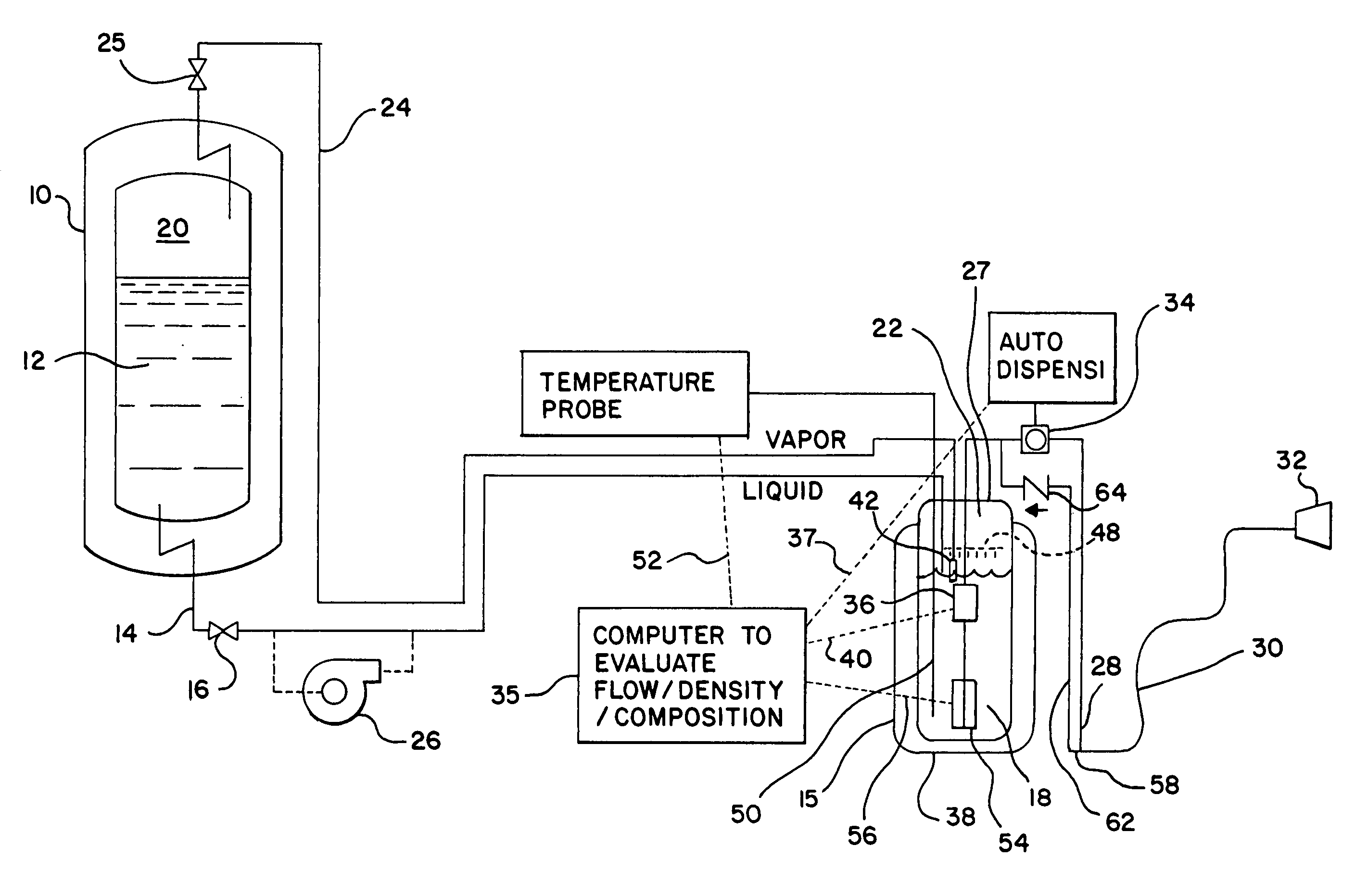
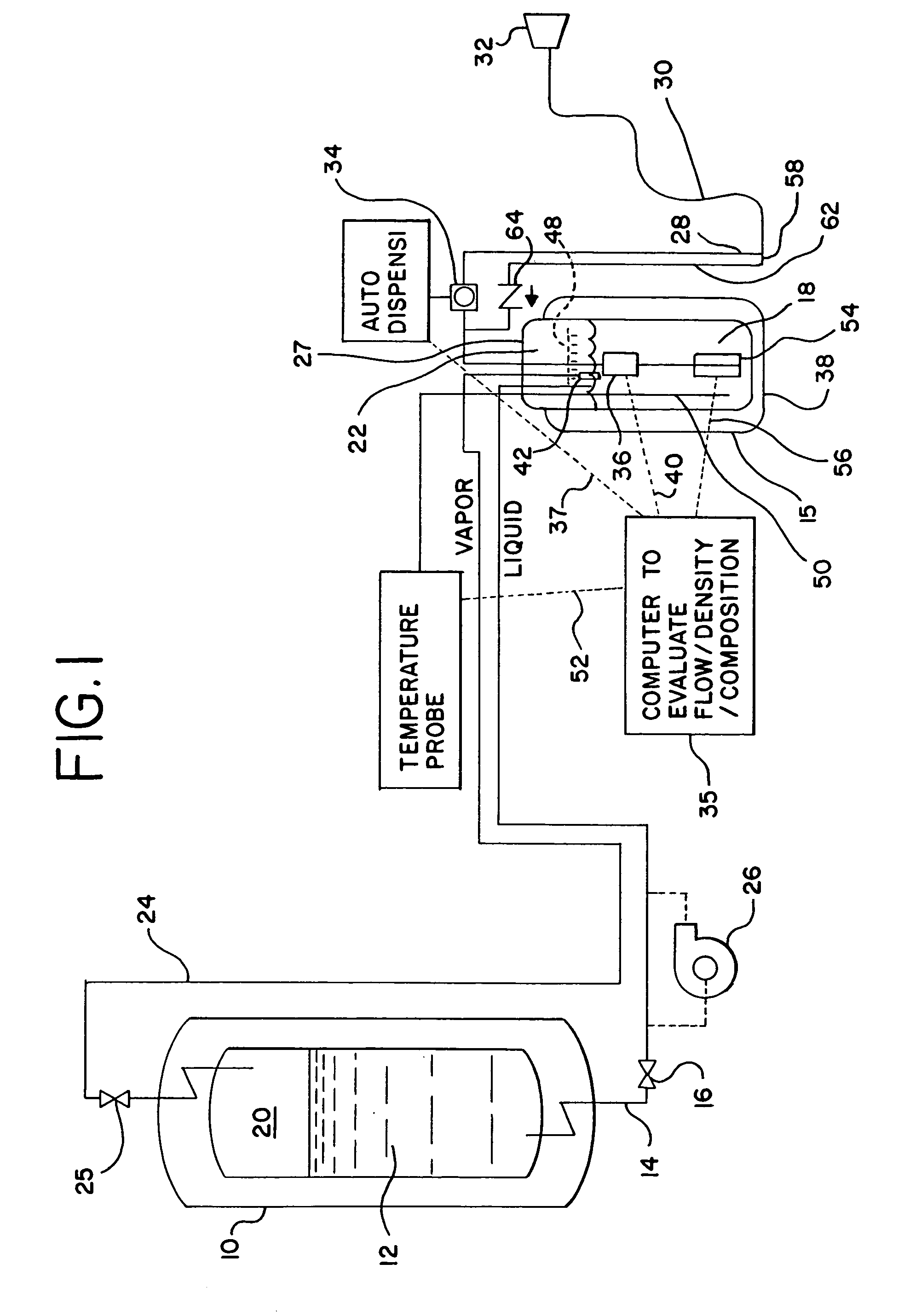
[0026]FIG. 1 illustrates a cryogenic liquid dispensing system that is constructed in accordance with the present invention. The system delivers a metered quantity of cryogenic liquid to a use device, such as a vehicle. While the remaining portion of the discussion will refer to Liquid Natural Gas (LNG) as the cryogenic liquid, it is to be understood that the invention could be used to dispense alternative cryogenic liquids.

[0027]The system of FIG. 1 includes a jacket-insulated bulk storage tank 10 for storing a large volume of LNG 12. An insulated line 14 connects the storage tank to 10 to a meter sump 15 and includes a shut-off valve 16. Meter sump 15 is partially filled with LNG 18 and the vapor spaces 20 and 22 of storage tank 10 and meter sump 15, respectively, are connected by a vapor return line 24, which also includes a shut-off valve 25. Meter sump 15 features a jacketed construction for insulation purposes and a removable lid 27 to allow service access.

[0028]A cryogenic liq...


PUM


Abstract

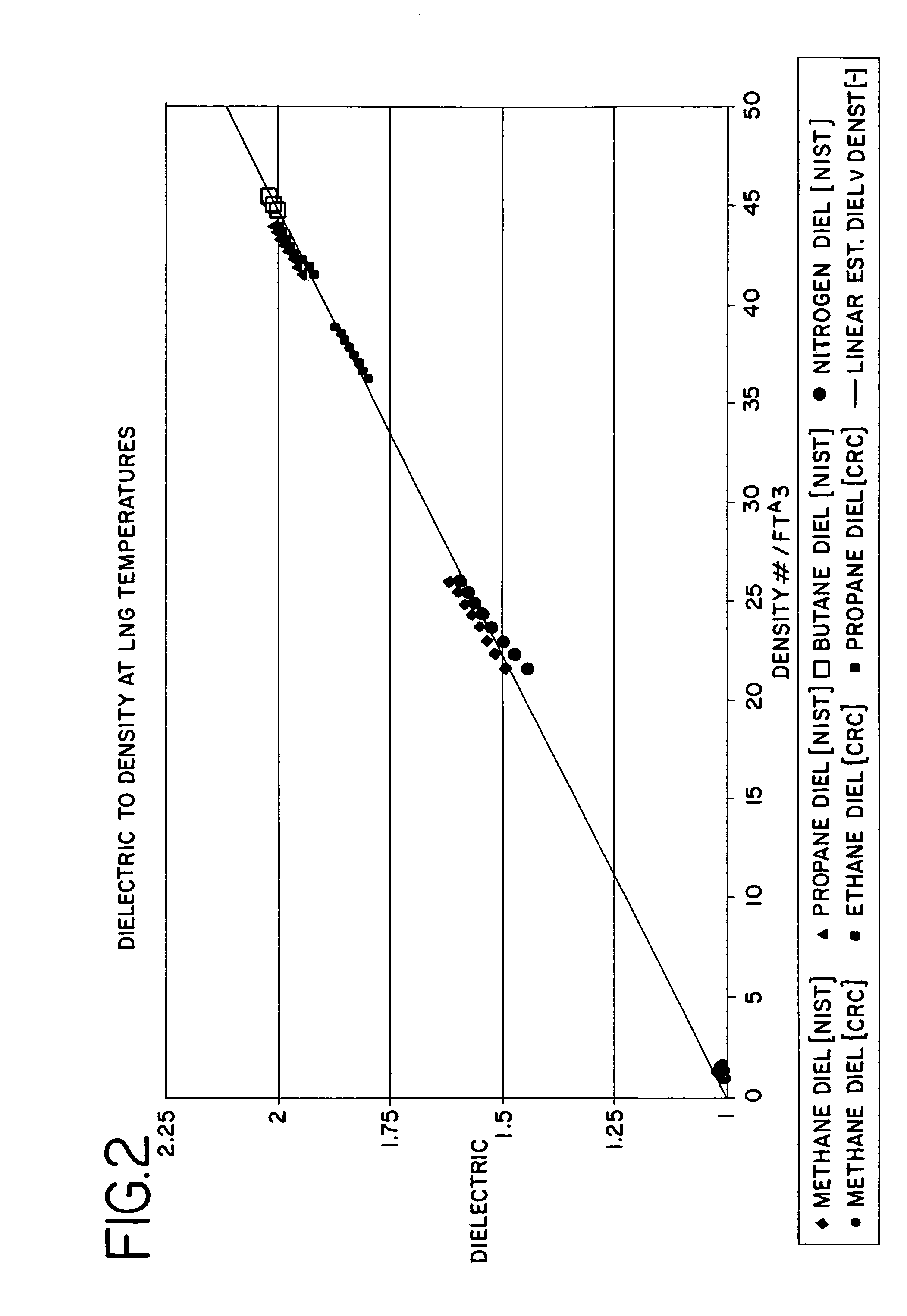
A system for dispensing cryogenic liquid to a use device includes a bulk storage tank providing LNG to a sump containing a meter submerged in LNG. A temperature probe is also submerged in the LNG. A dispensing line is positioned between the meter and dispensing hose and includes a dispensing valve. A drain line bypasses the dispensing valve and features a check valve so that LNG trapped in the hose after dispensing is returned to the sump due to pressurization by ambient heat. A capacitance probe is submerged in the LNG in the sump and provides a dielectric that is compared by a microprocessor with the dielectric for pure methane at the same temperature to determine the purity of the LNG. An approximate linear relation between density and dielectric may be used to determine density and mass flow for the LNG from the measured dielectric. Alternatively, a density compensation factor based upon the dielectrics may be calculated and applied to the density of pure methane to obtain the density and mass flow of the LNG. A further alternative embodiment substitutes a compensating meter for the capacitor and the equations for the resulting two meters may be solved to determine density and mass flow for the LNG.

Description

CROSS REFERENCE TO RELATED APPLICATIONS[0001]This application is a divisional application of U.S. patent application Ser. No. 10 / 366,743, filed on Feb. 13, 2003 U.S. Pat. No. 6,732,594, which is a divisional application of U.S. patent application Ser. No. 09 / 632,604, filed on Aug. 4, 2000, issued as U.S. Pat. No. 6,595,048.BACKGROUND OF THE INVENTION[0002]The present invention relates generally to delivery systems for cryogenic liquids and, more particularly, to a system for dispensing and accurately metering a cryogenic liquid, such as liquid natural gas, to a use device.[0003]Liquid natural gas (LNG) is a plentiful, environmentally friendly and domestically available energy source and, therefore, is an attractive alternative to oil. As a result, LNG is increasingly being used as a fuel for vehicles. This is especially true for fleet and heavy duty vehicles.[0004]A key issue in the commercialization of LNG is the ability to accurately meter and dispense it. The National Institute o...

Claims


Application Information

Patent Timeline
IPC IPC(8): F17C13/00F17C13/02F17C9/00G01F1/34B67D7/08G01F1/42G01F1/50G01F1/88G01N27/22
CPCF17C9/00F17C13/026F17C13/028G01F1/88F17C2221/033F17C2223/0153F17C2223/0161F17C2223/043F17C2223/046F17C2270/0168
Inventor DRUBE, THOMAS K.DRUBE, PAUL A.EMMER, CLAUS D.BILY, GILBERT J.GAMBLE, JESSE
Owner CHART INC
Learn More