Method and apparatus for efficiently cooling motorcycle engines

a technology for cooling motorcycle engines and cooling chambers, applied in the field of motorcycling, can solve the problems of shortening the life of the engine, accelerating the friction and wear of the engine components, and not easily flowing through the small oil passages within the engine block

Inactive Publication Date: 2005-10-18
PETCHEL JOHN JOSEPH
View PDF5 Cites 24 Cited by
  • Summary
  • Abstract
  • Description
  • Claims
  • Application Information

AI Technical Summary

Benefits of technology

[0013]In a preferred embodiment of the present invention an oil-cooling system for lubricating oil of a vehicle engine is provided, the system comprising a radiator having an oil inlet and an oil outlet communicating with internal passages of the radiator, an electrically-operated fan interfaced to the radiator in a manner to urge air through the radiator over the internal passages, the fan turned on and off by a temperature sensitive switch sensing oil temperature, a valve having a first inlet, a first passage through the valve through a first chamber to a first outlet, a second inlet, a second passage through the valve through a second chamber to a second outlet, and a translatable valve closure element controlling a passage from the first chamber to the second chamber, and a temperature-operated translation element positioned in the first chamber in the path of oil entering the valve through the first inlet, and connected to the translatable valve element in a manner to progressively close the passage from the first chamber to the second chamber at higher oil temperature, and to progressively open the passage from the first chamber to the second chamber at lower oil temperature. The system is characterized in that, below a first oil temperature the passage between the first and the second chamber remains open allowing oil coming in the first inlet to bypass the radiator to the second outlet, the passage closes gradually as oil temperature rises, closes completely at the first oil temperature so that all oil coming in the first inlet must pass through the radiator and none may bypass, and in that the temperature-sensitive switch operating the fan causes the fan to start at a second oil temperature higher than the first oil temperature, enhancing ability of the radiator to cool the oil.

Problems solved by technology

Lubricating engine oil at ambient temperature has higher viscosity than at engine operating temperature, and because of this heavier consistency of cold oil, it does not flow easily through small oil passages within the engine block or oil cooling system.
For example, if the running motorcycle is stopped at a stop light or in traffic, or for any other reason during engine operation, cooling air is not adequately flowing around the finned cylinders and other portions of the engine, the temperature of the engine and lubricating oil may rise quickly to the point of oil thermal breakdown temperature, which quickly accelerates engine component friction and wear, significantly shortening the life of the engine.
Such an arrangement, however, has significant drawbacks in that oil cooling unit, for example, by being mounted unprotected on the front of the frame of the motorcycle, is exposed to damage from rocks, tar, and other road debris that may be kicked by the front tire of the motorcycle during operation, or by other vehicles sharing the road with the motorcycle.
Another drawback in current art oil coolers and diverter apparatus is that, as equal amounts of oil are diverted to the oil cooler and by-passed back to the reservoir, the relatively excessive amount of oil pumped through the oil cooler at cold startup extends the period of time required for reaching the recommended operating temperature of the oil.

Method used


Image

  • Method and apparatus for efficiently cooling motorcycle engines
  • Method and apparatus for efficiently cooling motorcycle engines
  • Method and apparatus for efficiently cooling motorcycle engines

Examples


Embodiment Construction

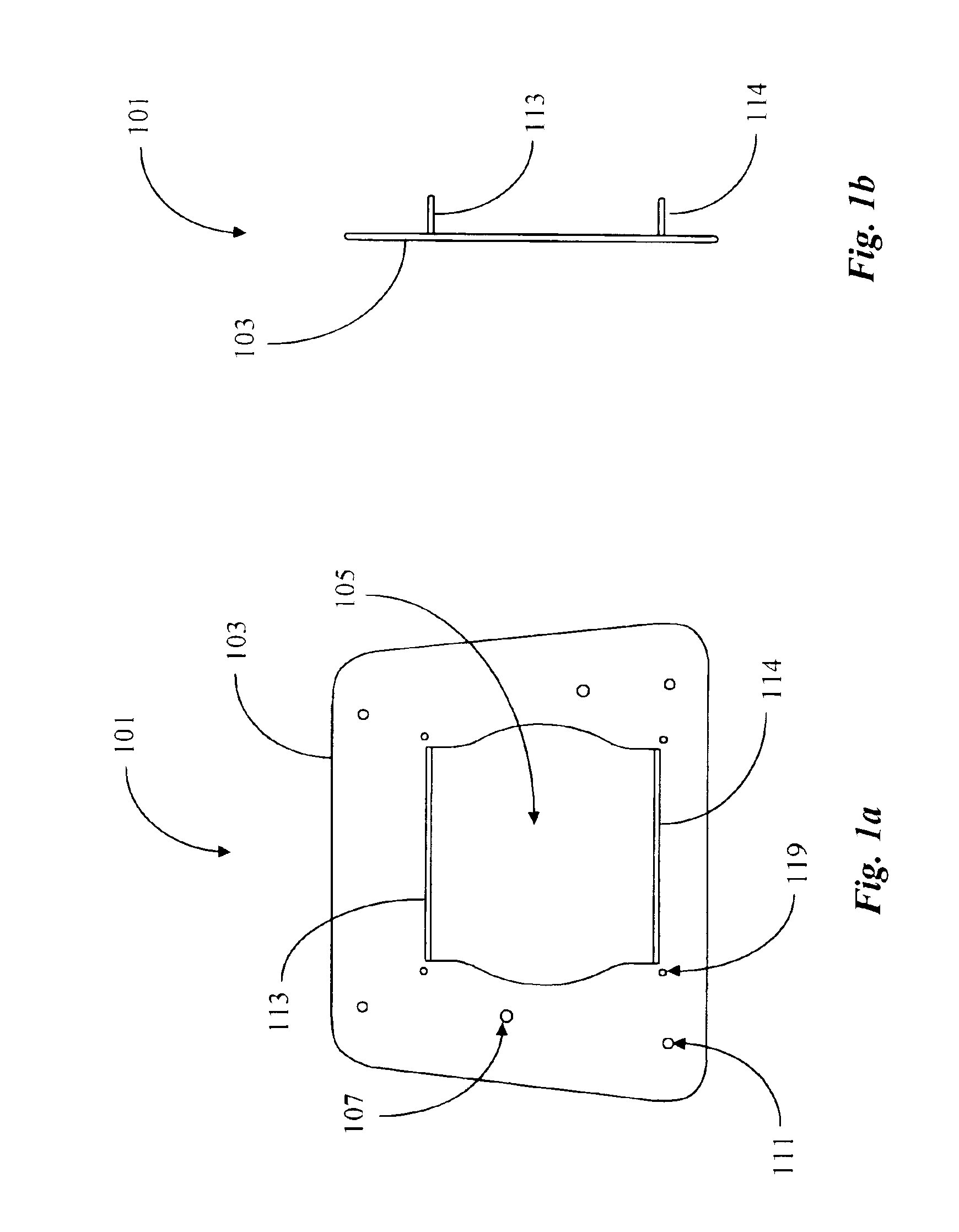
[0031]Referring now to FIG. 1a, the inventor first illustrates a mounting plate 101 provided for mounting an improved oil cooling unit to the front of a motorcycle. Plate 101 is in this example roughly trapezoidal in shape, the nonparallel sides extending upward from the bottom edge to form a smaller upper edge, and has four rounded corners. Plate 101 is designed for mounting to the front frame members of a motorcycle frame, particularly a pair of down tubes at the front of the frame, and the non-parallel sides are accordingly angled to align approximately with the angle between the pair of down tubes of the motorcycle frame. Since such an angle may vary from motorcycle model to model, and it is desirable for the edges of the plate to align with the edges of the frame when the plate is attached to the frame, the angle of the non-parallel sides of plate 101 may vary accordingly in alternative embodiments, and is therefore not particularly important in the scope and spirit of the pres...


PUM


Abstract

A method for managing oil temperature for a vehicle engine comprises the steps of (a) determining a preferred temperature window for oil in operation of the vehicle, comprising a first, lower temperature, and a second, higher temperature; (b) pumping oil from the vehicle engine to a control valve controlling oil passage into a radiator, and bypassing the radiator via a by-pass passage in the control valve more than seventy-percent of the oil to return to the vehicle engine without passing through the radiator upon cold start-up; (c) closing the bypass passage at the first oil temperature, forcing all oil entering the control valve to pass through he radiator before returning to the vehicle engine; (d) starting a forced-air fan at the second temperature to urge ambient air through air passages of the radiator, thereby enhancing ability of the radiator to cool the oil passing through.

Description

FIELD OF THE INVENTION[0001]The present invention is related to motorcycles, and pertains more particularly to oil cooling for air-cooled and other motorcycle engines.BACKGROUND OF THE INVENTION[0002]Many types of motorcycles exist which utilize a variety of engine types and operating temperature regulating apparatus and methods. Some motorcycles employ water cooling systems through the use of radiators and water passages within the engine block and other engine or transmission components. By far the most common type of motorcycle engine today, however, is an air-cooled engine comprising a lightweight aluminum engine block and cooling fins integrated around cylinders to dissipate accumulated heat from the engine generated from combustion and component friction within the engine.[0003]Notably, motorcycles manufactured by Harley-Davidson Motorcycle Company of Milwaukee, Wis. have large displacement, air-cooled four stroke engines which, as is true for the vast majority of motorcycle e...

Claims


Application Information

Patent Timeline
Patent Type & Authority Patents(United States)
IPC IPC(8): F01M5/00F01M1/00F01M1/12F01P11/08F01P5/02F01P5/04F01M1/10F02B61/00F02B61/02
CPCF01M1/12F01M5/007F01M1/10F01M2001/123F01M2001/126F01P11/08F01P2005/046F02B61/02
Inventor MOSS, MARLON EUYVON
Owner PETCHEL JOHN JOSEPH
Why Eureka
Try Eureka