Device and method for forming a circumferential conduction block in a pulmonary vein

a technology of circumferential conduction and pulmonary vein, which is applied in the field of surgical methods, can solve the problems of cardiac arrhythmias, generally believed to be entirely effective, proarrhythmias and long-term inefficacy

Inactive Publication Date: 2005-10-18
RGT UNIV OF CALIFORNIA
View PDF3 Cites 229 Cited by
  • Summary
  • Abstract
  • Description
  • Claims
  • Application Information

AI Technical Summary

Benefits of technology

[0010]The “maze procedure” as performed in the left atrium generally includes forming vertical incisions from the two superior pulmonary veins and terminating in the region of the mitral valve annulus, traversing the inferior pulmonary veins en route. An additional horizontal line also connects the superior ends of the two vert

Problems solved by technology

Cardiac arrhythmias, and atrial fibrillation in particular, persist as common and dangerous medical ailments, especially in the aging population.
However, such pharmacological solutions are not generally believed to be entirely effective in many cases, and may in some cases result in proarrhythmia and long term inefficacy.
However, more recent reports predict that the surgical “maze” procedure may be substantially efficacio

Method used


Image

  • Device and method for forming a circumferential conduction block in a pulmonary vein
  • Device and method for forming a circumferential conduction block in a pulmonary vein
  • Device and method for forming a circumferential conduction block in a pulmonary vein

Examples


Embodiment Construction

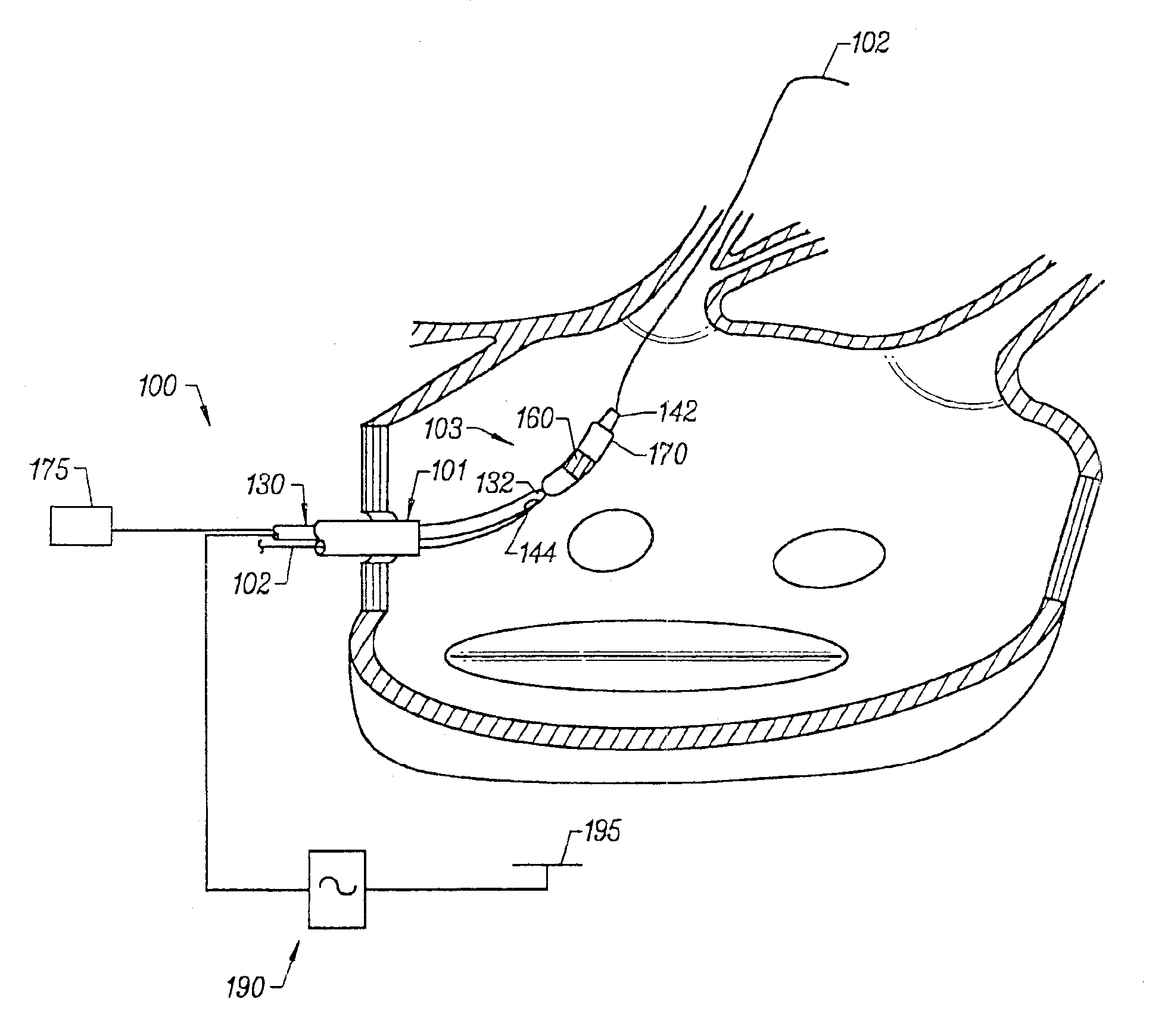
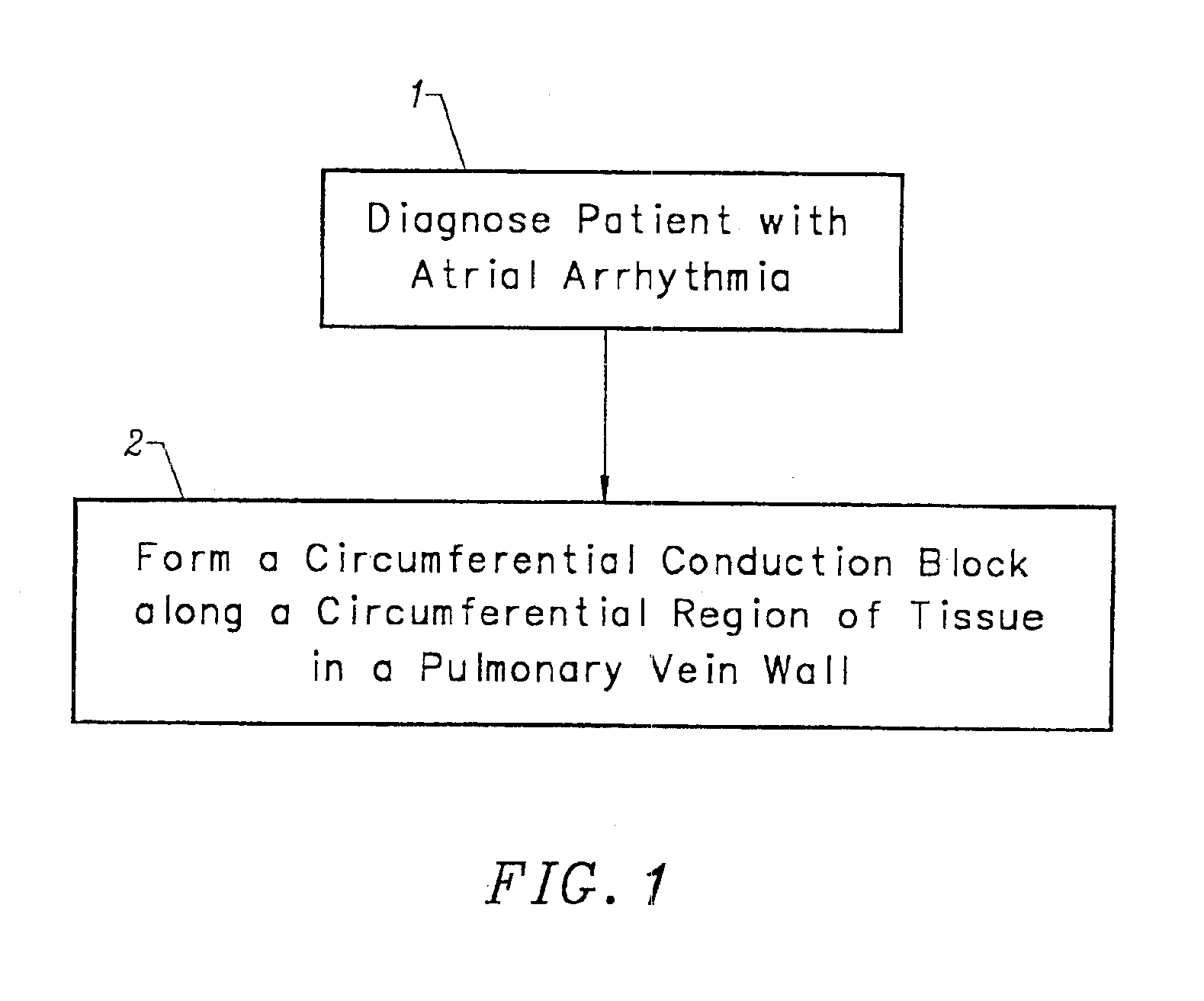
[0055]As diagrammatically illustrated in the flow diagram of FIG. 1, the present invention is a method for treating patients diagnosed with atrial arrhythmia by forming a circumferential conduction block in a pulmonary vein which blocks electrical conduction along the longitudinal axis of the pulmonary vein wall and into the left atrium.

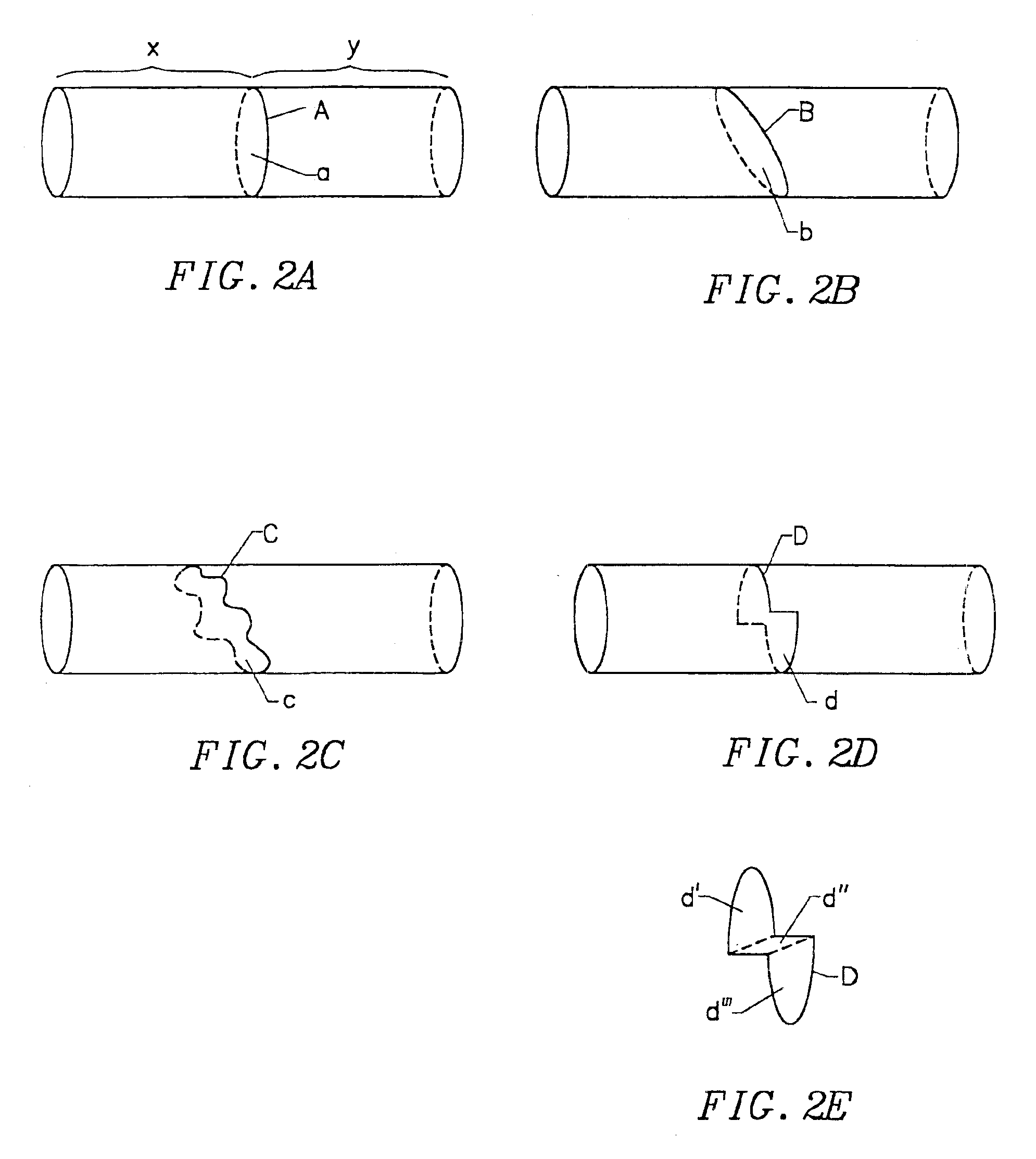
[0056]The terms “circumference” or “circumferential”, including derivatives thereof, are herein intended to mean a continuous path or line which forms an outer border or perimeter that surrounds and thereby defines an enclosed region of space. Such a continuous path starts at one location along the outer border Or perimeter, and translates along the outer border or perimeter until it is completed at the original starting location to enclose the defined region of space. The related term “circumscribe,” including derivatives thereof, is herein intended to mean to enclose, surround, or encompass a defined region of space. Therefore, according to these d...


PUM

PropertyMeasurementUnit
Electrical conductivityaaaaaaaaaa
Electrical conductoraaaaaaaaaa
Energyaaaaaaaaaa

Abstract

This invention is a method for treating a patient diagnosed with atrial arrhythmia by forming a circumferential conduction block along a circumferential path of tissue in a pulmonary vein wall that circumscribes the pulmonary vein lumen and transects the electrical conductivity of the pulmonary vein such that conduction is blocked along the longitudinal axis of the vein wall and into the left atrial wall. The method is performed to treat a patient with a focal arrythmogenic origin along the pulmonary vein wall by either ablating the focal origin or by isolating the focal origin from the atrial wall with the circumferential conduction block. The circumferential conduction block is also formed in a pulmonary vein in order to bridge the adjacent ends of two linear lesions, wherein each linear lesion is formed to extend between the pulmonary vein and another adjacent pulmonary vein in a less-invasive “maze”-type procedure. A circumferential ablation element in a circumferential ablation device assembly is used in a percutaneous translumenal catheter technique in order to form the circumferential conduction block in the pulmonary vein wall.

Description

CROSS-REFERENCE TO RELATED APPLICATIONS[0001]This application is a continuation of application Ser. No. 09 / 642,251 filed on Aug. 17, 2000, now U.S. Pat. No. 6,502,576, incorporated herein by reference, which is a continuation of application Ser. No. 09 / 384,727 filed on Aug. 27, 1999, now U.S. Pat. No. 6,305,378, incorporated herein by reference, which is a continuation of application Ser. No. 08 / 889,835 filed on Jul. 8,1997, now U.S. Pat. No. 6,012,457, incorporated herein by reference. This application is also a continuation-in-part of application Ser. No. 09 / 357,184 filed on Jul. 19, 1999, now U.S. Pat. No. 6,471,697, incorporated herein by reference, which is a continuation of application Ser. No. 08 / 853,861 filed on May 9, 1997, now U.S. Pat. No. 5,971,983, incorporated herein by reference.TECHNICAL FIELD[0002]The present invention is a surgical method. More specifically, it is a method for treating atrial fibrillation by creating a circumferential conduction block in a pulmonar...

Claims


Application Information

Patent Timeline
IPC IPC(8): A61B18/08A61B18/04A61B18/14A61M25/10A61B17/22A61B17/00A61N7/02A61N7/00A61F2/958
CPCA61B18/10A61B18/1492A61M25/1002A61B18/08A61B18/1815A61B2017/00243A61B2017/22038A61B2017/22054A61B2017/22067A61B2018/00011A61B2018/00083A61B2018/00107A61B2018/00148A61B2018/0016A61B2018/00214A61B2018/0022A61B2018/00273A61B2018/00285A61B2018/00291A61B2018/00351A61B2018/00369A61B2018/00375A61B2018/00577A61B2018/00642A61B2018/00797A61B2018/00815A61B2018/00821A61B2018/00839A61B2018/00898A61B2018/00994A61B2018/1407A61B2218/002A61M2025/1075A61M2210/125A61N7/022
Inventor LESH, MICHAEL D.
Owner RGT UNIV OF CALIFORNIA
Why Eureka
Try Eureka