Carrying assembly and method for securement of electronic devices

a technology for carrying assemblies and electronic devices, which is applied in the direction of garments, fishing, containers, etc., can solve the problems of not being able to quickly access electronic devices, not being able to easily remove carrying assemblies from belts or pants, and often cumbersome devices, so as to achieve simple and less expensive construction, quick and easy removal, and minimal effort

Inactive Publication Date: 2005-10-18
GARMIN
View PDF23 Cites 75 Cited by
  • Summary
  • Abstract
  • Description
  • Claims
  • Application Information

AI Technical Summary

Benefits of technology

[0009]A carrying assembly of the present invention overcomes the above-identified problems and provides a distinct advance in the art of carrying assemblies for electronic devices. More particularly, a first preferred embodiment of the present invention provides a carrying assembly that includes a rear panel, a spring component, a retainer button, and a base for securely clipping the assembly and the device to a user's clothing, such as the user's belt or a waist of the user's pants. The carrying assembly also includes a plurality of serrated teeth provided on a locking button and the retainer button for rotational adjustment of the electronic device by the user so that the user may rotate the assembly to a comfortable position. Furthermore, the carrying assembly provides for receipt of the locking button in a U-shape...

Problems solved by technology

One problem presented with carrying such an electronic device is securement of and accessibility to the electronic device.
Unfortunately, these devices are often cumbersome and do not allow quick access to the electronic device.
For example, some carrying assemblies are...

Method used


Image

  • Carrying assembly and method for securement of electronic devices
  • Carrying assembly and method for securement of electronic devices
  • Carrying assembly and method for securement of electronic devices

Examples


Embodiment Construction

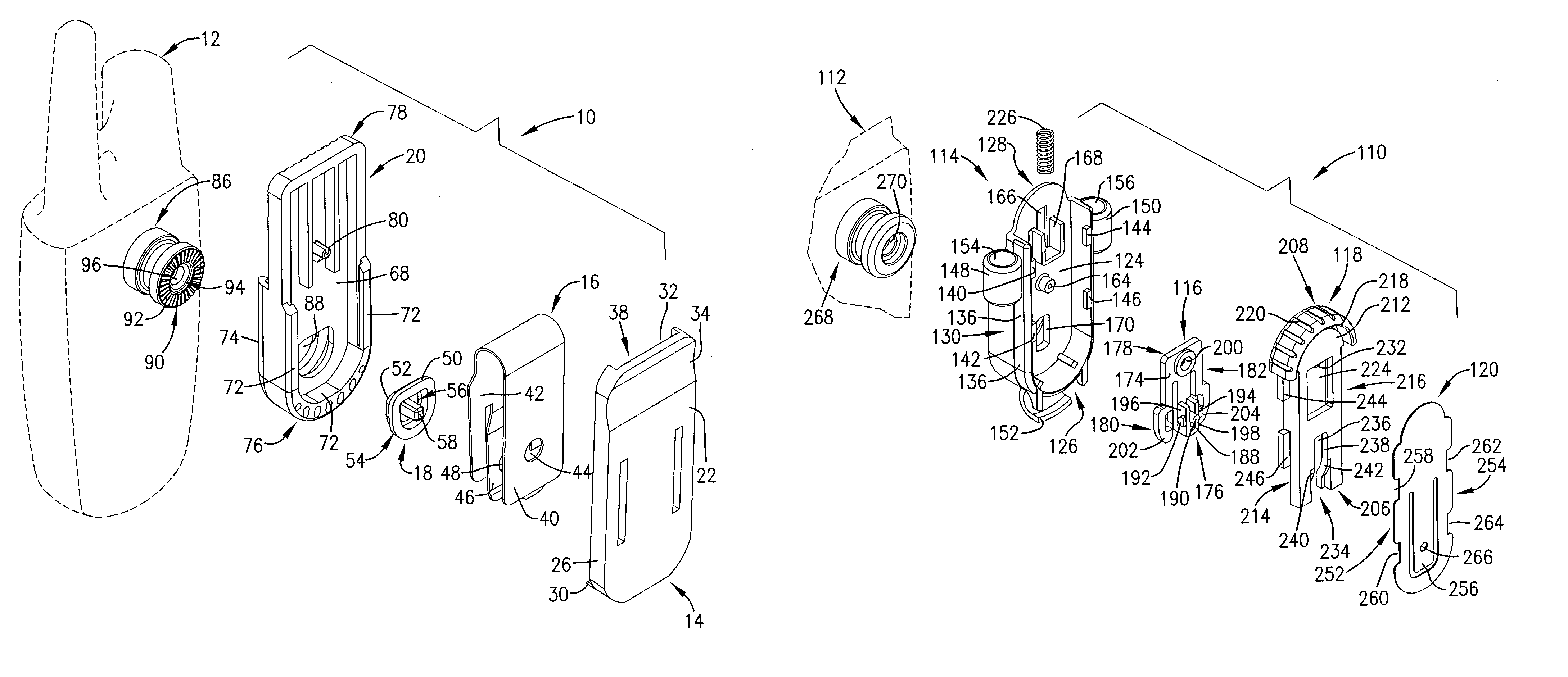
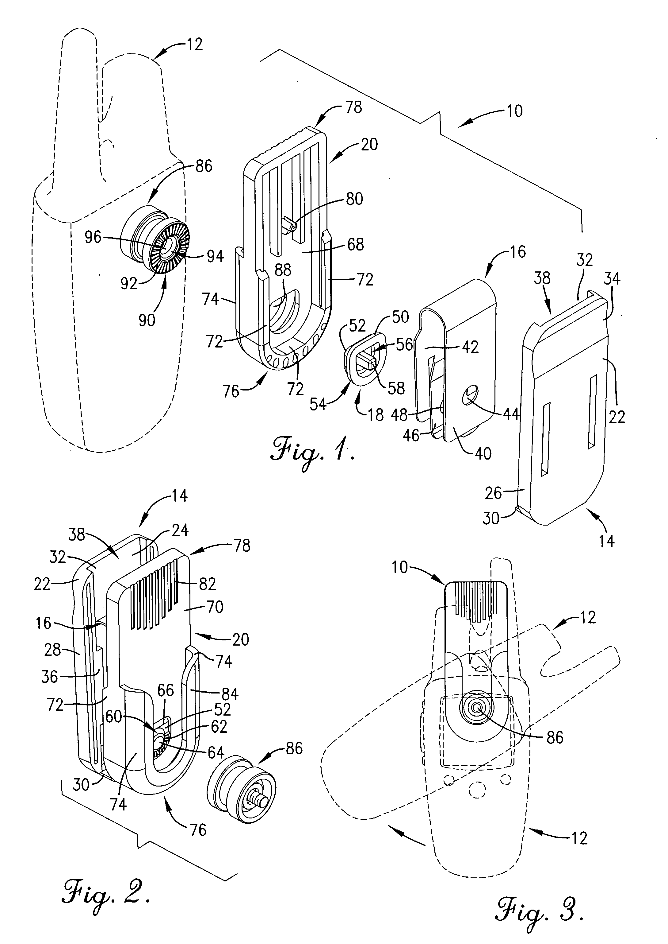
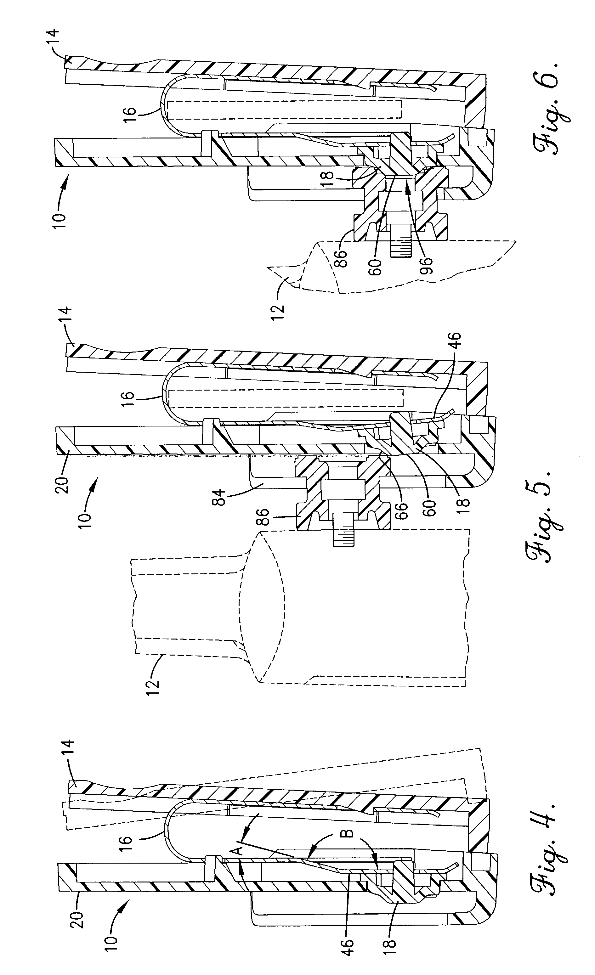
[0025]Turning now to the drawings, and particularly FIGS. 1–6, a carrying assembly 10 constructed in accordance with a first preferred embodiment of the present invention is illustrated. The carrying assembly 10 is particularly adapted for securing an electronic device 12, such as a mobile telephone, a GPS receiver unit, a PDA, or a pager, to a user's belt or a waist of the user's pants. As can best be seen in FIGS. 1 (in view from right to left) and 2 (in view from left to right), the carrying assembly 10 broadly comprises a rear panel 14, a spring component 16, a retainer button 18, and a base 20.

[0026]The rear panel 14 is generally rectangular in shape and has opposed planar rear and front faces 22 and 24, respectively, a first and a second side wall 26 and 28, respectively, a bottom wall 30, and a top wall 32. The rear face 22 preferably includes a trough-like shallow indentation 34 for receipt of the user's fingers in placement or removal of the carrying assembly 10. The first ...


PUM


Abstract

A carrying assembly (10,110) having an easy release clip for carrying of an electronic device (12,112) is disclosed. In both a first and a second preferred embodiment, the easy release clip of the carrying assembly (10,110) allows a user to insert and remove the electronic device (12,112) in one step and without having to depress a release key. In the first preferred embodiment, the carrying assembly (10) is adjustable so that the electronic device (12) may be positioned in a horizontal position, a vertical position, or any position between horizontal and vertical. The carrying assembly (10) broadly comprises a rear panel (14), a spring component (16) including an integral leaf spring (46), a retainer button (18), and a base (20). In a second preferred embodiment, the carrying assembly (110) is fitted to a lanyard so that the electronic device (112) may be worn around the user's neck. The carrying assembly (110) broadly comprises a base (114), a catch (116), an actuator (118), and a rear panel (120) having an integral leaf spring (256).

Description

BACKGROUND OF THE INVENTION[0001]1. Field of the Invention[0002]The present invention relates to carrying assemblies for securing or carrying portable electronic devices. More particularly, the present invention relates to a carrying assembly operable to quickly and easily release an electronic device from the carrying assembly and to adjustably position the device in a preferred position.[0003]2. Description of Prior Art[0004]Portable electronic devices are well-known in the art, examples of which include mobile telephones, pagers, personal digital assistants (“PDAs”), global positioning system (“GPS”) receiver units, etc. One problem presented with carrying such an electronic device is securement of and accessibility to the electronic device. A user of the electronic device desires to carry the electronic device in such a manner to prevent dropping, misplacing, or damaging the electronic device, while at the same time maintaining quick access to the electronic device.[0005]Prior a...

Claims


Application Information

Patent Timeline
IPC IPC(8): A45F5/00A45F5/02
CPCA45F5/02A45C2011/002Y10S224/93Y10T24/44444Y10T24/44427Y10T24/1382Y10T24/1391
Inventor MUDD, JOHN J.BURRELL, JONATHAN C.WHITESIDE, JOHN B.LAMMERS-MEIS, DAVID
Owner GARMIN
Why Eureka
Try Eureka