Temperature controlled reaction vessel

a reaction vessel and temperature control technology, applied in the field of chemical or biological reactors, can solve the problems of insufficient heat of reactants, method fails to address the heat of reaction, temperature of reactants to produce undesirable products, etc., and achieves improved heat transfer, increased section modulus of vessel walls, and improved mechanical strength of reactor walls

Inactive Publication Date: 2005-10-18
ARENCIBIA ASSOCS
View PDF26 Cites 32 Cited by
  • Summary
  • Abstract
  • Description
  • Claims
  • Application Information

AI Technical Summary

Benefits of technology

[0008]The present invention is an insulated chemical or biological reactor (such as a fermenter) system comprising a reaction vessel, an evacuated insulation shell, a plurality of temperature controlling mixing baffles immersed in the reactor contents and a temperature controlling helical channel coil outside of the reactor but inside the evacuated shell. A device designed to control the separation of phases of the working fluid chosen is required and may be external to the reactor. This device is referred to as the phase separator and has two outlets, one for each phase of the working fluid. The temperature controlling mixing baffles are designed to accept the working fluid in a single phase proceeding from one outlet of the phase separator and to, in turn, cause this fluid to change phase therein without carryover of any of the inlet fluid in the evolved phase. The changing of phase of the working fluid in the temperature controlling mixing baffles takes place at a uniform temperature, the level of which is dictated by the thermodynamic properties of the working fluid selected. The temperature controlling mixing baffles are referred to as isothermal mixing baffles. The channel coil is adapted to accept a circulating fluid, specifically of a single phase evolved by the mixing baffles and the other outlet of the phase separator. The particular working fluid selected depends on the intended temperature control purposes, that is whether heating or cooling is desired and the degree of heating or cooling needed. The channel coil is affixed to the outside wall of the reactor in a helical configuration and adapted to receive the single phase of the working fluid evolved by the mixing baffles and the other outlet of the phase separator which flows spirally upward or downward around the outside of the reactor. The channel coil is shaped to have two straight, parallel sides of the coil in contact with the reactor, normal to the surface of the outside wall of the reactor. This right angle contact between the channel coil and reactor wall increases the section modulus of the vessel wall, and thereby increases the mechanical strength of the reactor wall under external pressure. The wall can thus be made thinner to promote better heat transfer across the wall. The reactor, including the mixing baffles and the affixed coil, are together enclosed within an evacuated jacket.

Problems solved by technology

This method fails to address the heat of reaction, which is often responsible for the majority of heat produced or absorbed in a reaction.
The heat of reaction can then alter the temperature of the reactants to produce undesirable products.
Again, pre-adjustment of the temperature of reactants fails to adequately address this situation.
Further, complicated production processes may have exothermic and endothermic reactions taking place (usually at different times) as reactants are added or products withdrawn.
Pre-adjustment of reactant temperature is clearly totally inadequate in such situations.
The effectiveness of the jacket is limited by heat transfer properties which are in turn limited by mechanical design characteristics and geometry, including specifically vessel diameter and length.
Unfortunately, however, heat transfer and mechanical strength are competing values in reactor design.
For a given vessel diameter and length, the reactor wall may be thick enough to meet pressure and strength requirements, but too thick for optimal heat transfer between the jacket fluid and the reaction medium, as heat transfer is decreased with increased wall thickness.
As a consequence, the reactor contents can freeze along the inside of the reactor wall.
The formation of “ice” results in a thicker wall overall and decreased heat transfer efficiency, as well as potentially inconsistent reactor medium composition, and in some cases, destruction of some reactants or products through freezing.
This large increase in specific volume can lead to erratic heat transfer mechanisms and, consequently, poor reactor medium temperature control.

Method used


Image

  • Temperature controlled reaction vessel
  • Temperature controlled reaction vessel
  • Temperature controlled reaction vessel

Examples


Embodiment Construction

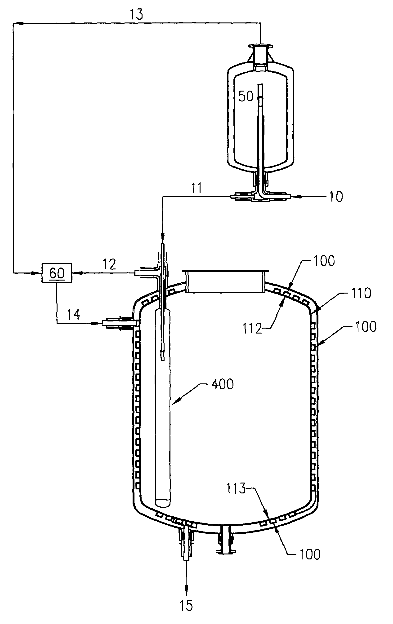
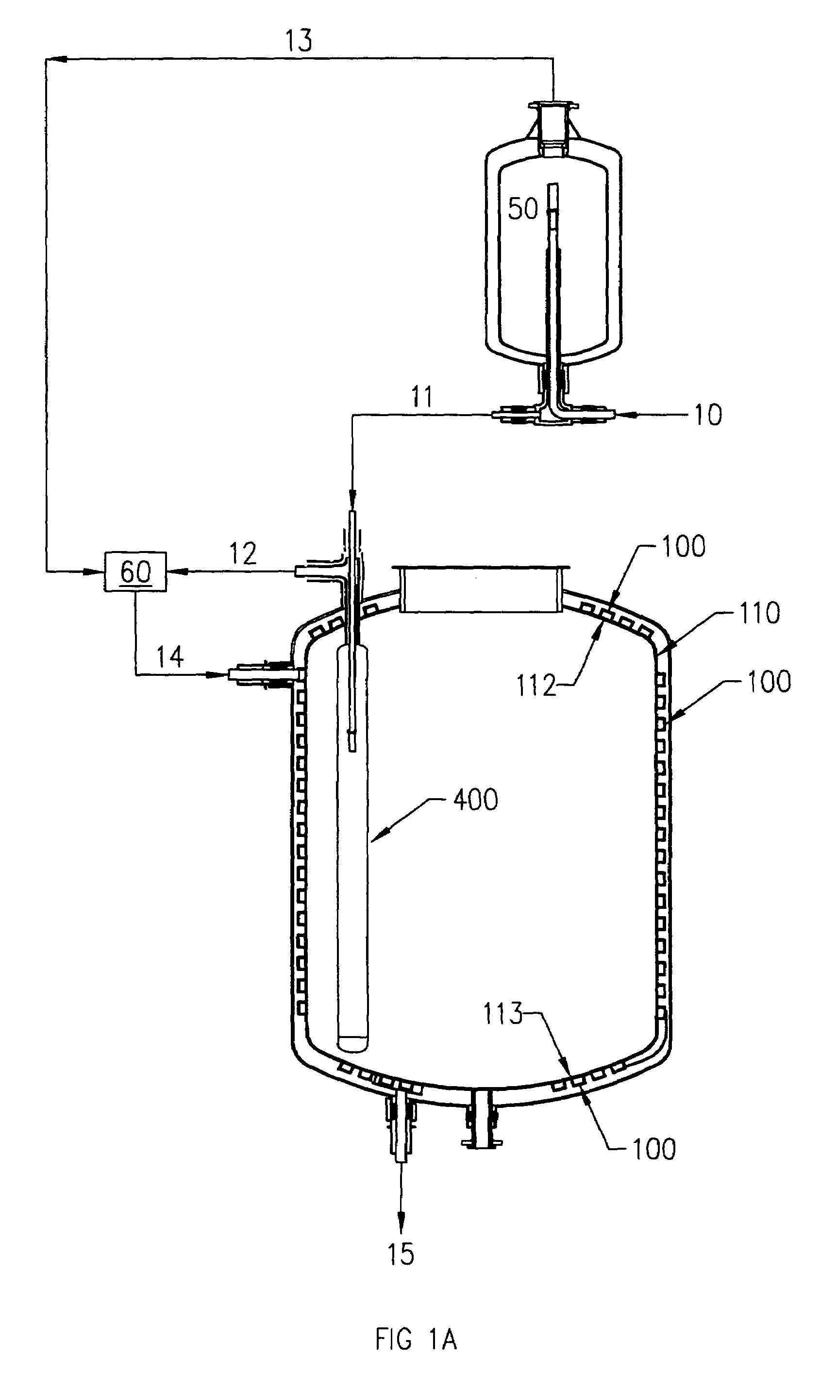
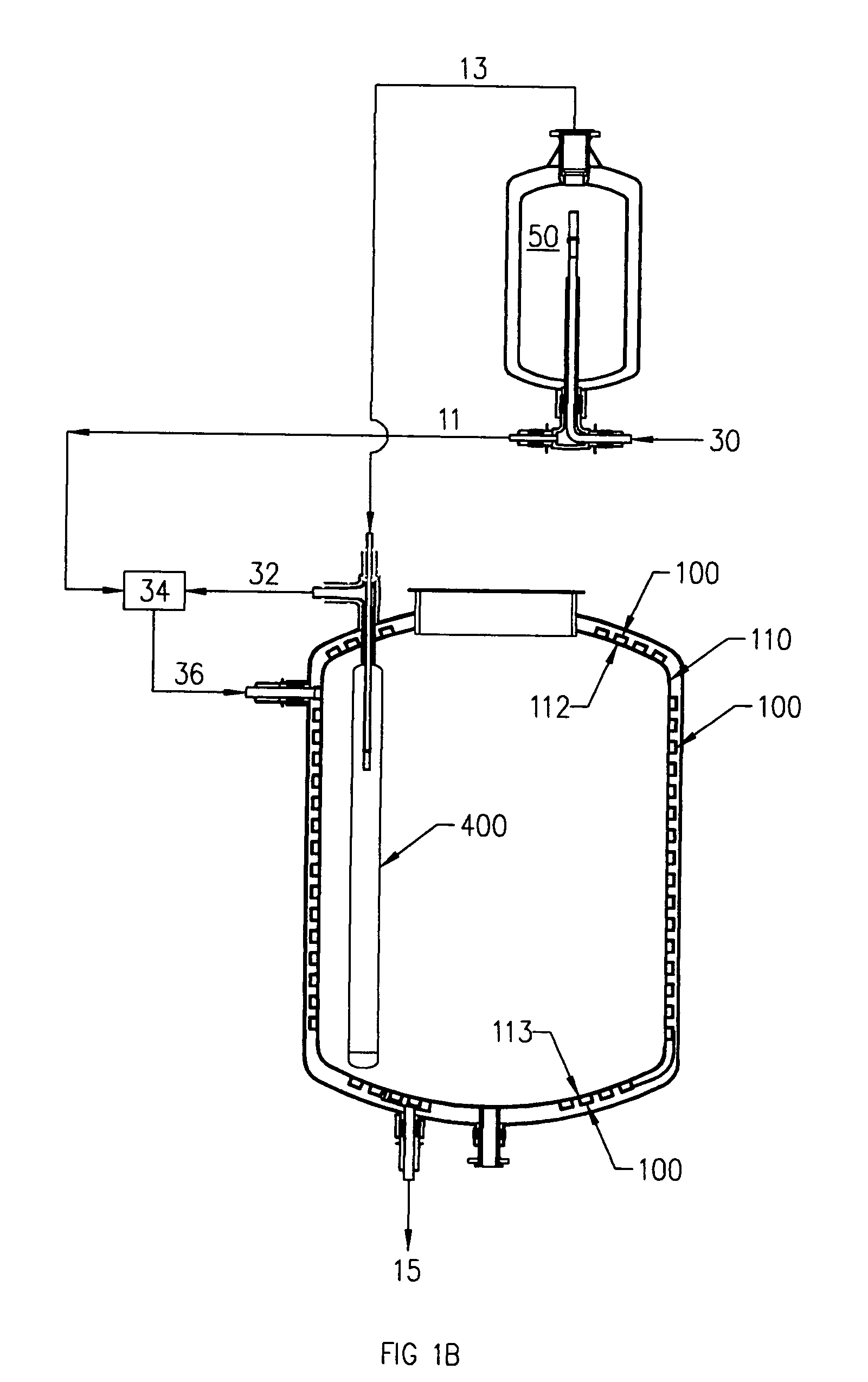
[0042]In the prior art, increasing reactor size (diameter and length) affects heat transfer to the reactor contents as the distance from the reactor external jacket to the centerline of the reactor increases (this is the radius). The present invention eliminates this problem as the insertion of isothermal mixing baffles in the reactor contents brings heat sinks (cooling) or sources (heating) to the contents as required to achieve temperature uniformity.

[0043]Since most reactors are basically cylindrical, there is a circular interface region between the highest level of the content and the empty (head) space above it. The ratio of this content / head space cross-sectional area to the volume of the content increases with increasing level of content.

[0044]With good mixing and temperature uniformity, the reactions in the content occur homogeneously in the bulk of the liquid content. Evolved gases, however, must pass through the circular content / head space interface. Therefore, as the reac...


PUM

PropertyMeasurementUnit
pressuresaaaaaaaaaa
temperatureaaaaaaaaaa
thicknessaaaaaaaaaa

Abstract

A reaction vessel which includes internally placed temperature controlling mixing baffles in which liquid is boiled, resulting in an isothermal heat sink. The energy of vaporization is supplied by the reaction vessel contents. The vapor produced by the boiling is directed to channel coils which surround the outside of the reaction vessel wall. The channel coils contact the outside wall of the reaction vessel perpendicularly, and provide mechanical support for the reaction vessel. The mechanical support from the channel coils allows for a decrease in the thickness of the reaction vessel wall and corresponding increased heat transfer efficiency between the channel coil contents and the reaction vessel contents. The entire above described apparatus is enclosed within an evacuated shell to provide additional insulation. The apparatus includes a gravitationally powered device that ensures that saturated or sub-cooled liquid enters the isothermal mixing baffles, thus guaranteeing that isothermal phase change will occur therein.

Description

CROSS-REFERENCE TO RELATED APPLICATION[0001]This application is a continuation-in-part of U.S. application Ser. No. 08 / 878,372 filed Jun. 18, 1997 now abandoned.FIELD OF THE INVENTION[0002]The present invention relates to chemical or biological reactors generally, and in particular to an apparatus for controlling the temperature within a chemical reactor.BACKGROUND OF THE INVENTION[0003]Temperature control of a chemical reaction is often the key to obtaining desired products. Where the temperature is controlled, generally the reaction kinetics are controlled. Where the reaction kinetics are controlled, undesired intermediates and byproducts can be diminished or avoided. Traditional temperature control of industrial reactors is generally attained in one of two ways. One method is to control the temperature of the reactants as they enter the reactor. This method fails to address the heat of reaction, which is often responsible for the majority of heat produced or absorbed in a reactio...

Claims


Application Information

Patent Timeline
Patent Type & Authority Patents(United States)
IPC IPC(8): F28D21/00F28D5/00B01F27/91B01F33/40B01J19/00B01J19/18F28D1/06
CPCB01F7/1675B01F7/22B01F15/065B01F15/066B01J19/0013B01J19/0066B01J19/18F28D1/06B01F7/00633B01J2219/00078B01J2219/0009B01J2219/00128B01J2219/0013B01J2219/00153B01F27/191B01F27/86B01F27/91B01F35/93B01F35/92
Inventor ARENCIBIA, JR., JOSE P.
Owner ARENCIBIA ASSOCS
Why Eureka
Try Eureka