High magnification, four-group zoom lens
a zoom lens and high magnification technology, applied in the field of high magnification, can solve the problems of difficult to achieve high optical performance over the entire range of zoom and focus, difficult to achieve high resolution without reducing the absolute value of lateral color, etc., and achieve high magnification and large zoom ratio. , the effect of high performan
- Summary
- Abstract
- Description
- Claims
- Application Information
AI Technical Summary
Benefits of technology
Problems solved by technology
Method used
Image

Examples
embodiment 1
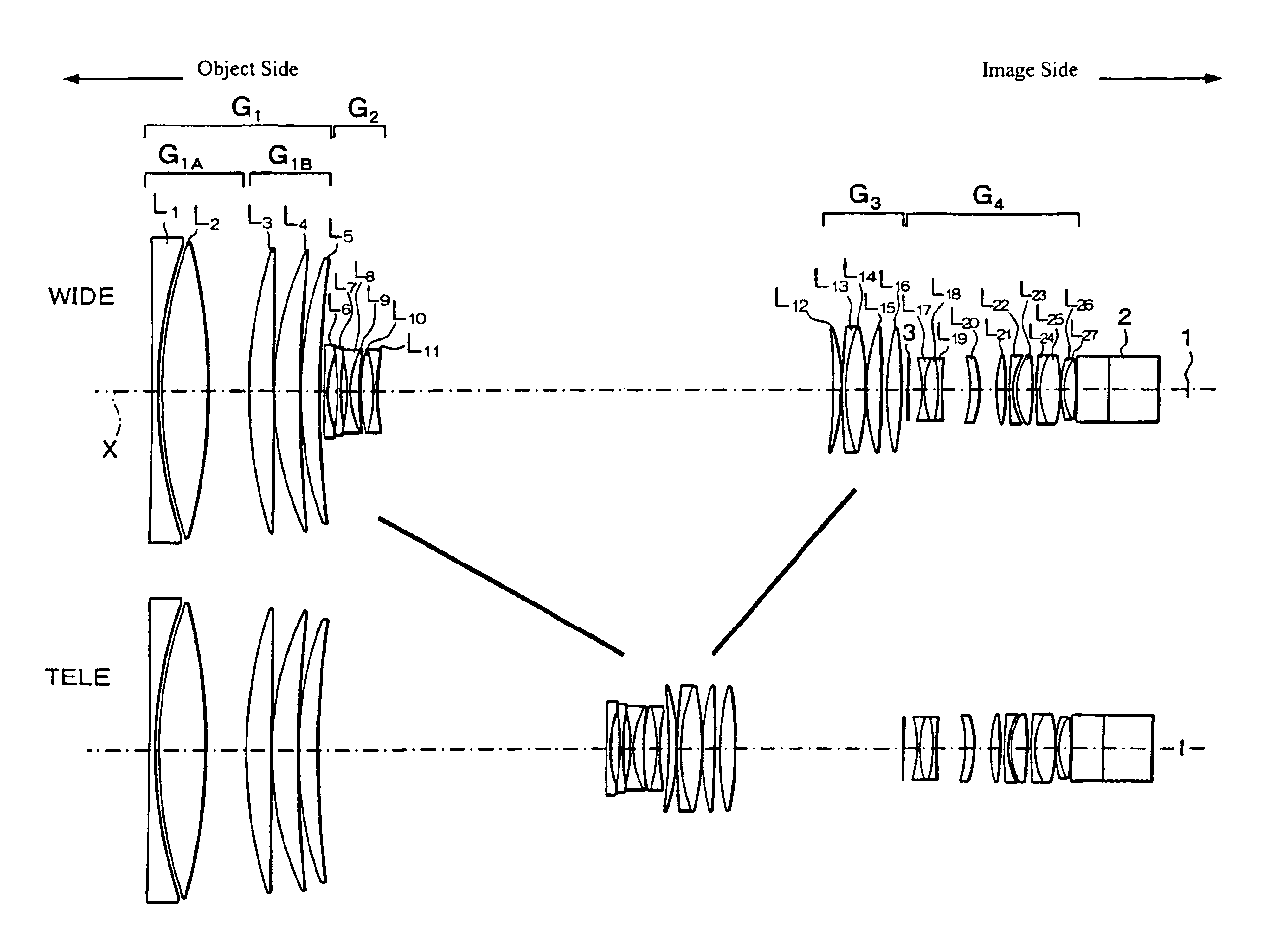
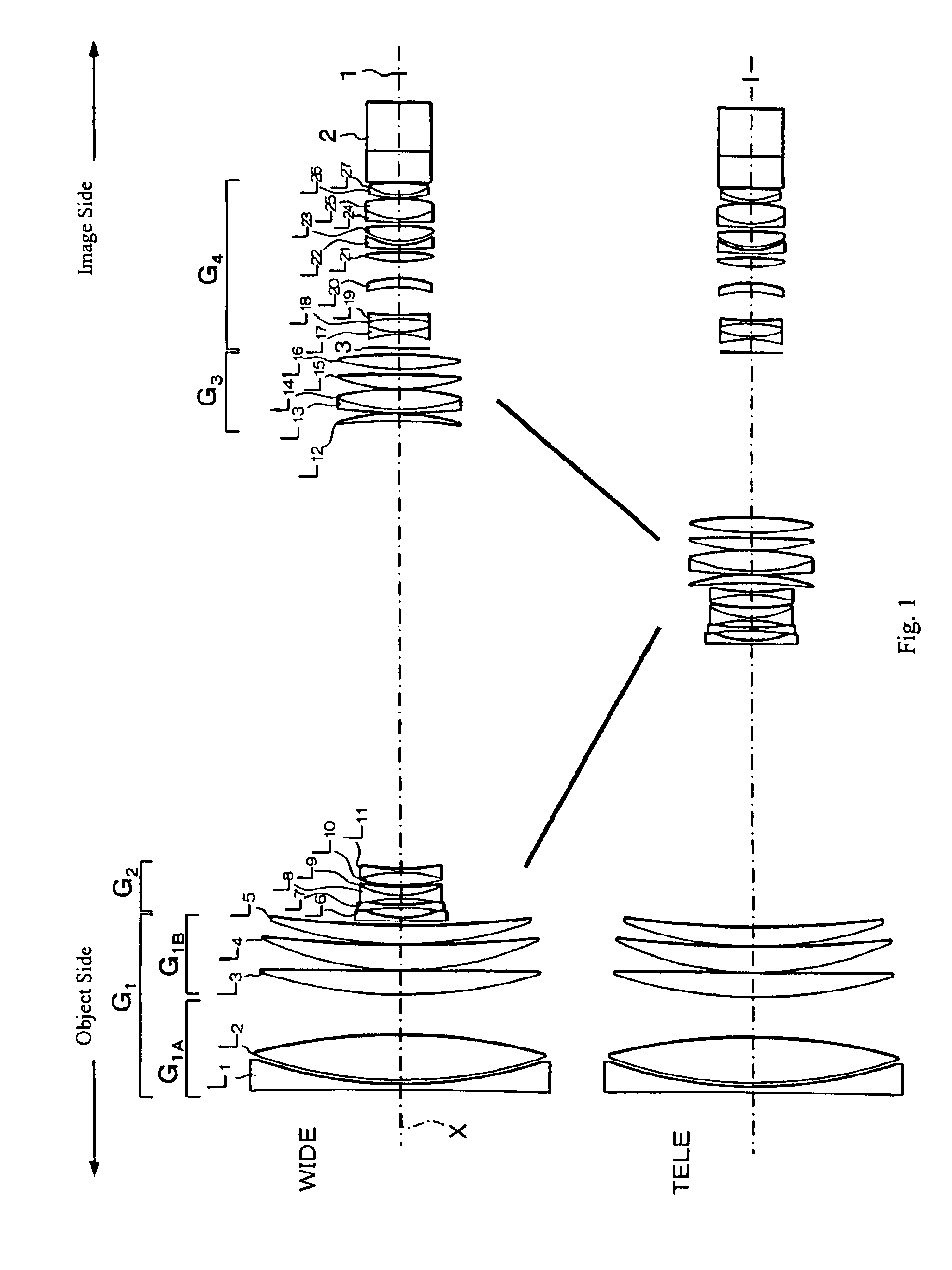
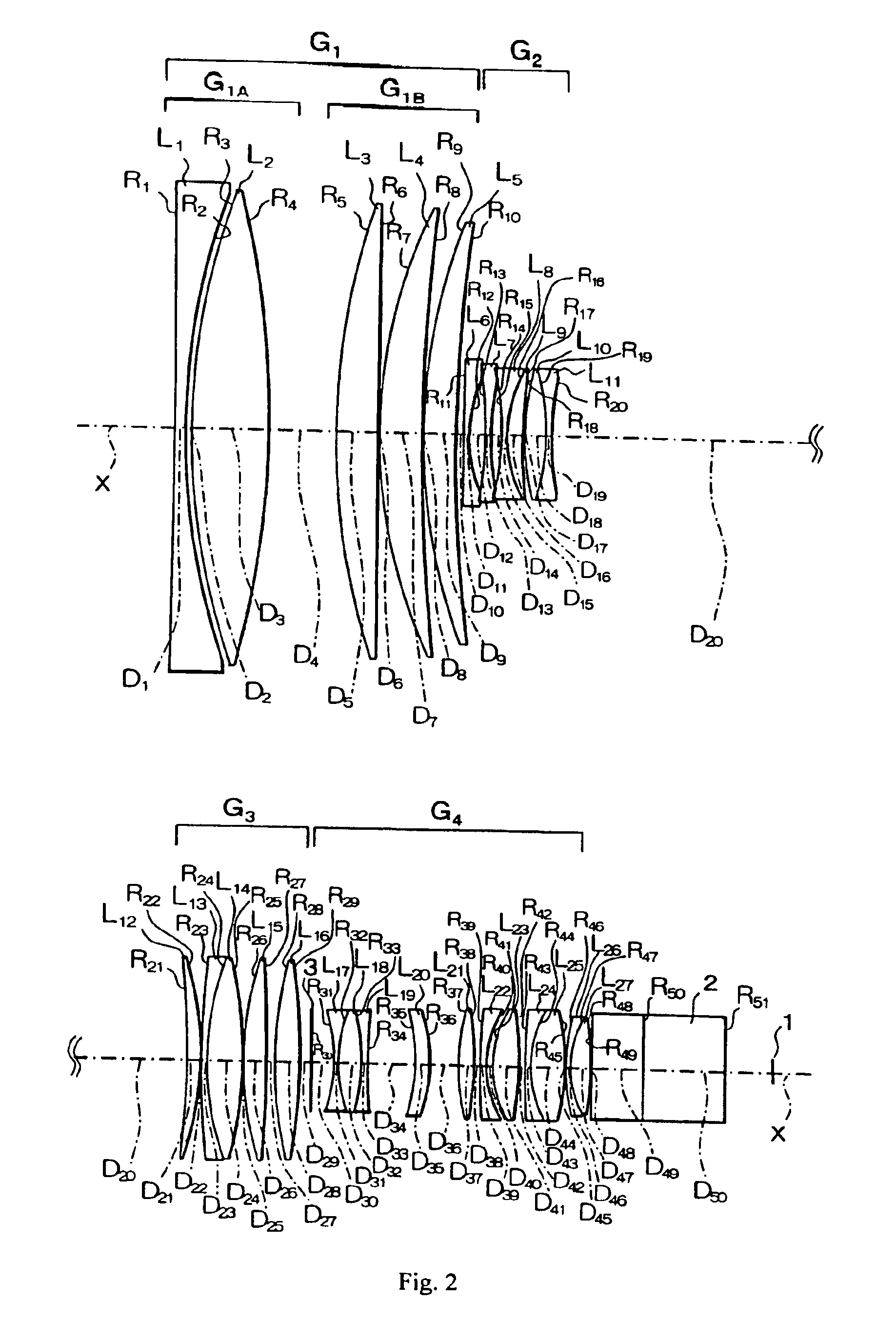
[0036]In Embodiment 1, as shown in FIGS. 1 and 2, the first lens group G1 includes, in order from the object side: a first lens element L1 that is biconcave having surfaces of different curvature and with its surface of greater curvature on the image side; a second lens element L2 that is biconvex having surfaces of different curvature and with its surface of greater curvature on the object side; a third lens element L3 of positive refractive power and a meniscus shape with its convex surface on the object side; a fourth lens element L4; and a fifth lens element L5. In the first lens group G1, the first lens element L1 and the second lens element L2 form a first lens subgroup G1A that is fixed during focusing. The third lens element L3, the fourth lens element L4, and the fifth lens element L5 form a second lens subgroup G1B that is moved as a unit during focusing.
[0037]The second lens group G2 includes, in order from the object side: a sixth lens element L6 of negative refractive p...
embodiment 2
[0048]Embodiment 2 is very similar to Embodiment 1 and therefore only the differences between Embodiment 2 and Embodiment 1 will be explained. In Embodiment 2, the sixth lens element L6, which is in the second lens group G2, is a biconcave lens element with its lens surface of greater curvature on the image side.
[0049]Table 3 below lists the surface number #, in order from the object side, the radius of curvature R (in mm) of each surface, the on-axis surface spacing D (in mm), as well as the refractive index Ne (at the e-line of 546.1 nm) and the Abbe number νd (at the d-line of 587.6 nm) of each lens element for Embodiment 2.
[0050]
TABLE 3#RDNeνd1−485.4704.4001.8039942.32515.4931.6263530.01428.6741.4349795.14−305.62727.5005564.96017.7671.4349795.16−640.7990.2507279.93218.7761.4349795.1877741.2120.2509189.01213.9001.4398695.010448.311D10 (variable)11−4629.9092.1001.8881340.91267.4546.84213−165.4712.0501.8201646.714141.6264.65315−111.8932.0201.7205647.91656.1936.9601.8550023.917278.9...
embodiment 3
[0056]Embodiment 3 is very similar to Embodiment 1 and therefore only the differences between Embodiment 3 and Embodiment 1 will be explained. FIG. 3 shows Embodiment 3. As shown in FIG. 3, the first lens group G1 of the zoom lens of Embodiment 3 includes only four lens elements, in order from the object side, a first lens element L1 having negative refractive power and a meniscus shape with its convex lens surface on the object side, second and third lens element L2 and L3 that are biconvex lens elements, each with its lens surface of greater curvature on the object side, and a fourth lens element L4 having positive refractive power and a meniscus shape with its convex lens surface on the object side. In the first lens group G1, the first lens element L1 and the second lens element L2 form a first lens subgroup G1A, which is fixed during focusing, and the third lens element L3 and the fourth lens element L4 form a second lens subgroup G1B, which is moved during focusing.
[0057]The s...
PUM
 Abstract
Description
Claims
Application Information
 - R&D
- Intellectual Property
- Life Sciences
- Materials
- Tech Scout
- Unparalleled Data Quality
- Higher Quality Content
- 60% Fewer Hallucinations
Browse by: Latest US Patents, China's latest patents, Technical Efficacy Thesaurus, Application Domain, Technology Topic, Popular Technical Reports.
© 2025 PatSnap. All rights reserved.Legal|Privacy policy|Modern Slavery Act Transparency Statement|Sitemap|About US| Contact US: help@patsnap.com