Methods and systems for multi-modality imaging

a multi-modality imaging and imaging method technology, applied in the field of imaging systems, can solve the problems of ct imaging being typically performed using a relatively expensive x-ray source, scan using a pencil-beam ct system typically taking a longer amount of time than scan using a typical ct system,

Inactive Publication Date: 2005-10-18
GE MEDICAL SYST GLOBAL TECH CO LLC
View PDF11 Cites 49 Cited by
  • Summary
  • Abstract
  • Description
  • Claims
  • Application Information

AI Technical Summary

Problems solved by technology

CT imaging is typically performed using a relatively expensive x-ray source and x-ray detector.
However, a scan using a pencil-beam CT system typically takes a longer amount of time than scans using typical CT systems.

Method used


Image

  • Methods and systems for multi-modality imaging
  • Methods and systems for multi-modality imaging
  • Methods and systems for multi-modality imaging

Examples


Embodiment Construction

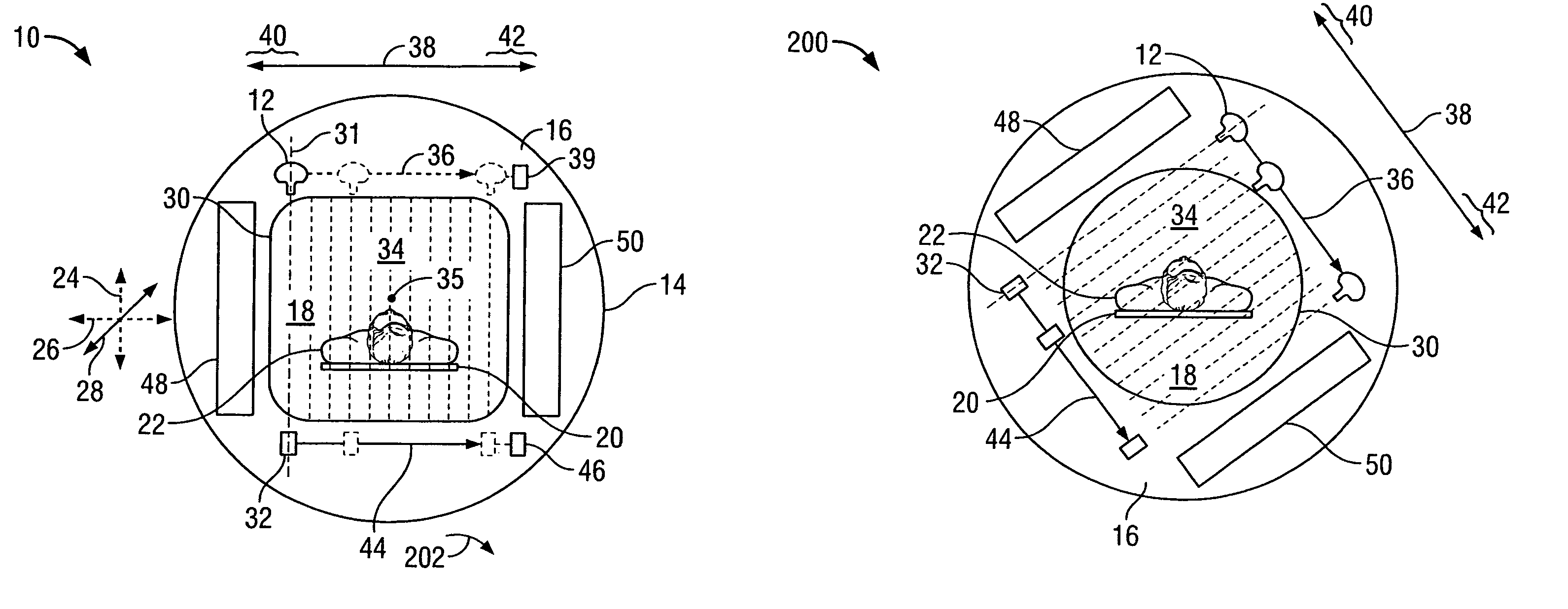
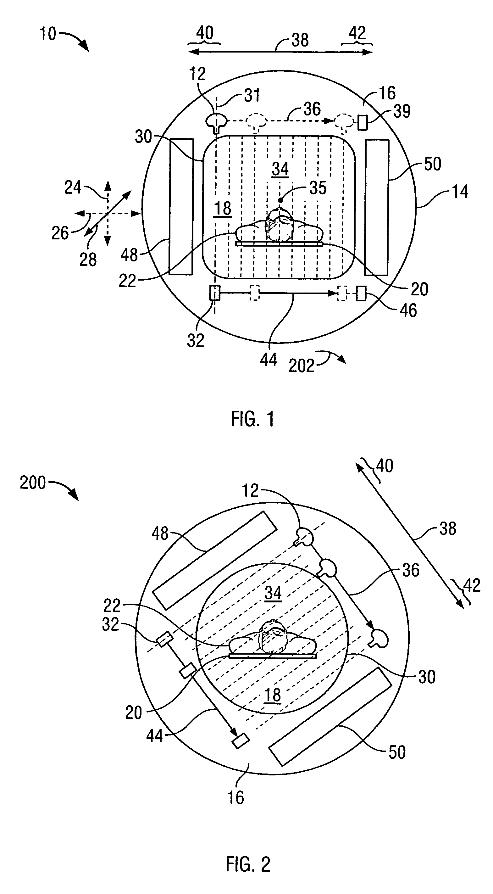
[0011]FIG. 1 is a schematic illustration of an imaging system 10 in accordance with an exemplary embodiment of the present invention. Imaging system 10 includes a x-ray source 12 mounted on a gantry 14. In the exemplary embodiment, gantry 14 includes a body 16 having an aperture 18 therethrough. In an alternative embodiment, gantry 14 may be fabricated from a plurality of gantry segments that may be separated from an adjacent segment by a space. A patient table 20 is configured to support and carry a patient 22 in a plurality of viewing positions within aperture 18. Patient table 20 includes a support mechanism (not shown) that is configured to support patient table 20 and move patient table 20 in any of at least three substantial orthogonal directions, including, for example, an up-down direction 24, a right-left direction 26 and a in-out direction 28. The support mechanism may control the motion of patient table 20 prior to a scan to align patient 22, during a scan to control a po...


PUM

PropertyMeasurementUnit
computed tomography imagingaaaaaaaaaa
medicine imagingaaaaaaaaaa
nuclear medicine imagingaaaaaaaaaa

Abstract

A method of examining a patient is provided. The method includes imaging a patient utilizing a computed tomography imaging modality, the patient between the pencil-beam x-ray source and the x-ray detector, and imaging the patient between the pencil-beam x-ray source and the x-ray detector using a nuclear medicine imaging modality.

Description

BACKGROUND OF THE INVENTION[0001]This invention relates generally to imaging systems capable of operation in multiple modalities, and more particularly to methods and systems for conducting a pencil-beam computed tomography (CT) scan in a multi-modality system.[0002]Multi-modality imaging systems are capable of scanning using different modalities, such as, for example, positron emission tomography (PET), single positron emission tomography (SPECT), computed tomography (CT), static x-ray imaging, and dynamic (fluoroscopy) x-ray imaging. In a multi-modal system (also referred to as a multi-modality system), a portion of the same hardware is utilized to perform different scans (e.g., an image produced by SPECT is processed and displayed respectively, by the same computer and display, as an image produced by CT). However, the data acquisition systems (also referred to as an “imaging assembly”) are different. For example, on a CT / SPECT system, a radiation source and a radiation detector ...

Claims


Application Information

Patent Timeline
Patent Type & Authority Patents(United States)
IPC IPC(8): A61B6/03A61B6/00G01N23/02G01N23/04G01N23/00G01T1/161G01T1/00G21K1/00G21K1/12H05G1/60H05G1/00G01T1/164
CPCA61B6/032A61B6/037A61B6/4071G01T1/1615G01T1/1642A61B6/5235
Inventor HOFFMAN, DAVID MICHAEL
Owner GE MEDICAL SYST GLOBAL TECH CO LLC
Why Eureka
Try Eureka