Cannister and upright vortex vacuum cleaners

a vacuum cleaner and upright technology, applied in the direction of cleaning filter means, separation processes, filtration separation, etc., can solve the problems of compromising the efficiency of the nozzl

Inactive Publication Date: 2005-10-25
DMR HLDG GROUP
View PDF22 Cites 19 Cited by
  • Summary
  • Abstract
  • Description
  • Claims
  • Application Information

AI Technical Summary

Benefits of technology

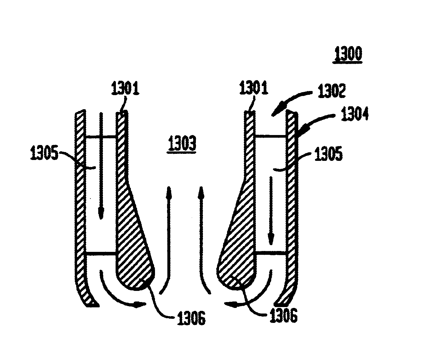
[0034]Described herein are embodiments that deal with both toroidal vortex vacuum cleaner nozzles and systems. The nozzles include simple concentric systems and more advanced, optimized systems. Such optimized systems utilize a thickened inner tube that is rounded off at the bottom for smooth airflow from the air delivery duct to the air return duct. It is also contemplated that the nozzle include flow straightening vanes to eliminate rotational components in the airflow that greatly harm efficiency. The cross section of the nozzle need not be circular, in fact, a rectangular embodiment is disclosed herein, and other embodiments are possible.
[0048]It is also an object of the present invention to provide non-rotating air with reduced dust content to re-cycle through the vacuum cleaner's toroidal vortex nozzle.

Problems solved by technology

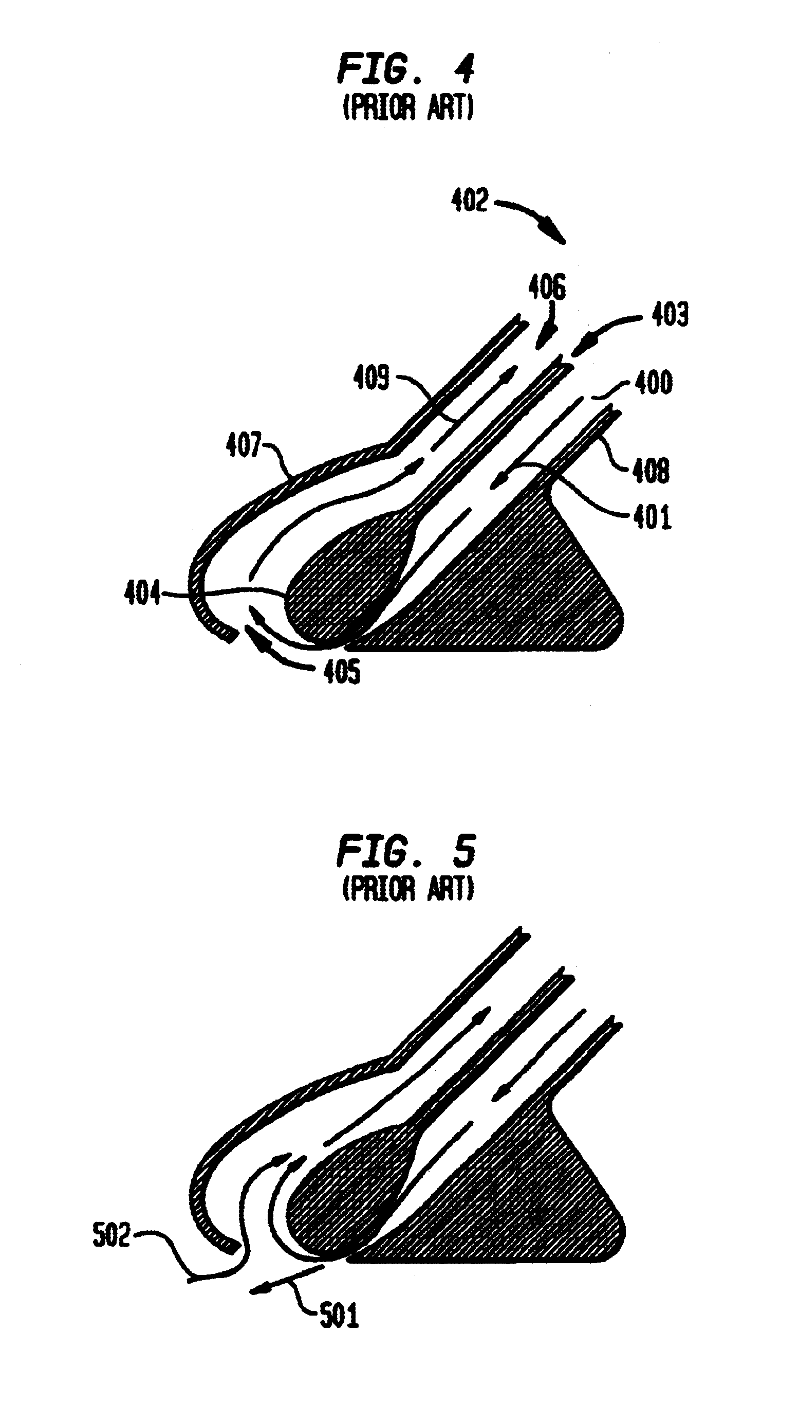
If air is rotating, a significant amount can be expelled from the annulus into the atmosphere, thus compromising the efficiency of the nozzle.

Method used


Image

  • Cannister and upright vortex vacuum cleaners
  • Cannister and upright vortex vacuum cleaners
  • Cannister and upright vortex vacuum cleaners

Examples


Embodiment Construction

[0077]As required, a detailed illustrative embodiment of the present invention is disclosed herein. However, techniques, systems and operating structures in accordance with the present invention may be embodied in a wide variety of forms and modes, some of which may be quite different from those in the disclosed embodiment. Consequently, the specific structural and functional details disclosed herein are merely representative, yet in that regard, they are deemed to afford the best embodiment for purposes of disclosure and to provide a basis for the claims herein which define the scope of the present invention. The following presents a detailed description of a preferred embodiment (as well as some alternative embodiments) of the present invention.

[0078]Certain terminology will be used in the following description for convenience in reference only and will not be limiting. The words “in” and “out” will refer to directions toward and away from, respectively, the geometric center of th...


PUM

PropertyMeasurementUnit
flexibleaaaaaaaaaa
pressureaaaaaaaaaa
pressuresaaaaaaaaaa

Abstract

The present invention relates to upright and cannister vacuum cleaners. The improved vacuum cleaners utilize toroidal vortex technology to provide efficient airflow in a sealed system. The sealed system prevents dust from escaping into the atmosphere and retains kinetic energy of flowing air. The present invention is also quieter, lighter, and simpler than conventional designs.

Description

CROSS REFERENCE TO OTHER APPLICATIONS[0001]This application is a continuation-in-part of application entitled “Toroidal Vortex Vacuum Cleaner Centrifugal Dust Separator,” U.S. patent application Ser. No. 10 / 025,376, filed Dec. 19, 2001, now U.S. Pat. No. 6,719,830, which is a continuation-in-part of application entitled “Toroidal Vortex Bagless Vacuum Cleaner,” U.S. patent application Ser. No. 09 / 835,084, filed Apr. 13, 2001, now U.S. Pat. No. 6,687,951, which is a continuation-n-part of application entitled “Toroidal and Compound Vortex Attractor,” U.S. patent application Ser. No. 09 / 829,416, filed Apr. 9, 2001, now U.S. Pat. No. 6,729,839, which is a continuation-in-part of application Ser. No. 09 / 728,602, now U.S. Pat. No. 6,616,094, filed Dec. 1, 2000, entitled “Lifting Platform,” which is a continuation-in-part of Ser. No. 09 / 316,318, now U.S. Pat. No. 6,595,753, filed May 21, 1999, entitled “Vortex Attractor.”TECHNICAL FIELD OF THE INVENTION[0002]The present invention relates ...

Claims


Application Information

Patent Timeline
Patent Type & Authority Patents(United States)
IPC IPC(8): A47L9/02A47L9/08A47L5/14A47L5/12
CPCA47L5/14A47L9/08Y10S55/03
Inventor ILLINGWORTH, LEWISREINFELD, DAVID
Owner DMR HLDG GROUP
Why Eureka
Try Eureka