Water heater flue with improved heat transfer

a technology of water heater flue and heat transfer, which is applied in the field of heat transfer to achieve the effect of improving the efficiency of water heaters

Active Publication Date: 2005-10-25
BOCK WATER HEATERS
View PDF15 Cites 15 Cited by
  • Summary
  • Abstract
  • Description
  • Claims
  • Application Information

AI Technical Summary

Benefits of technology

[0008]It is a feature of the present invention to improve the efficiency of a water heater b

Problems solved by technology

Second, the baffles mix the combustion gases within the flue, bringing more of the flue gases into contact w

Method used


Image

  • Water heater flue with improved heat transfer
  • Water heater flue with improved heat transfer
  • Water heater flue with improved heat transfer

Examples


Embodiment Construction

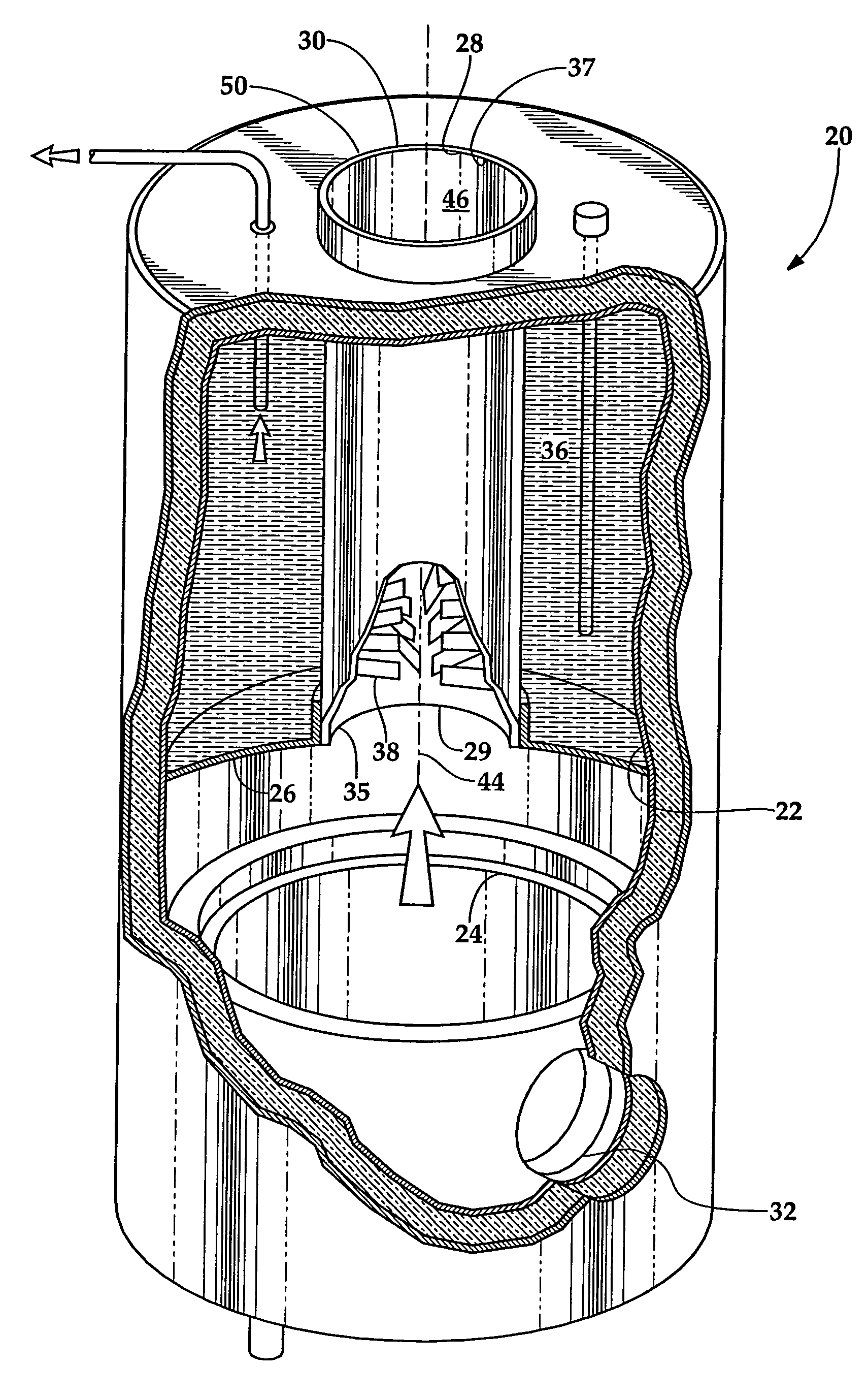
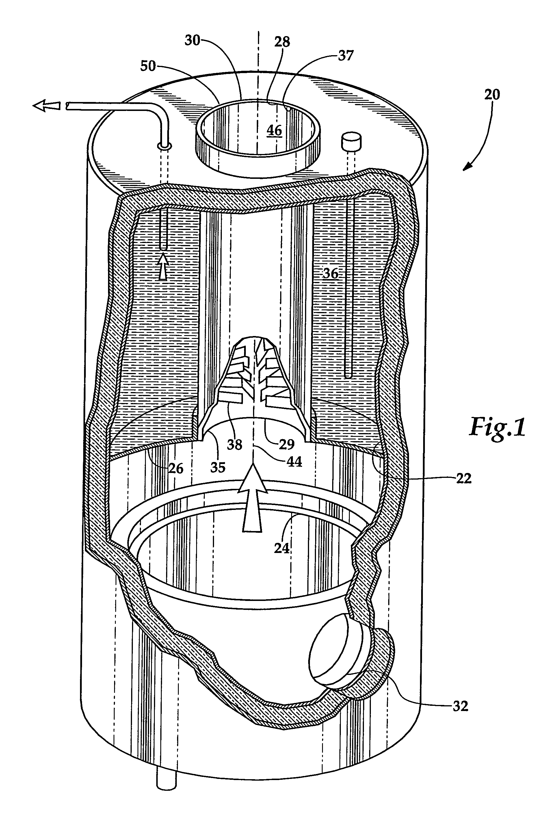
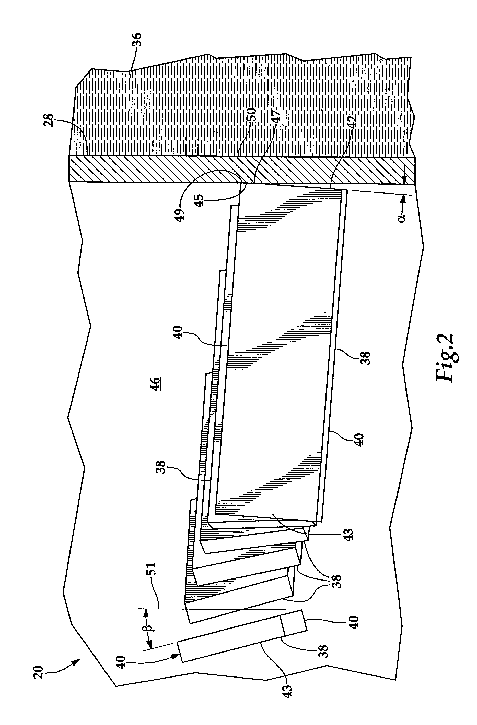
[0012]Referring more particularly to FIGS. 1–2, wherein like numbers refer to similar parts, a water heater 20 is shown in FIG. 1. The water heater 20 has a water tank 22 which is separated from combustion chamber 24 by a dome 26. A central mild steel flue 28 extends between an opening 29 in the dome 26 and the top 30 of the water heater tank 22. A burner (not shown) is positioned in an opening 32 leading into a combustion chamber 24 which may contain a ceramic crucible surrounded by insulating fiber or where the firebox may be formed by ceramic fiber insulation alone. The burner may operate on oil, natural gas or propane or other fuel. The exhaust gases from the burner flow upwardly through the central flue 28 from the flue inlet 35 to the flue outlet 37, exchanging heat with the water 36 contained within the water tank 22.

[0013]Heat is exchanged between the dome 26 and the central flue 28 and the water 36 contained in the water tank 22 of the water heater 20. As hot combustion gas...


PUM


Abstract

A water tank has a central flue to which clips are welded. The clips define baffles and are welded to have a greater heat transfer area where they are joined to the central flue. The individual clips are rectangular and are welded to the flue wall along one side at an angle of 4° rather than the 9° of the prior art so that the clip has a greater weld area. This greater weld area increases the thermal path between the clip and the wall of the central flue.

Description

CROSS REFERENCES TO RELATED APPLICATIONS[0001]This application is a continuation of U.S. application Ser. No. 10 / 922,441 filed Aug. 20, 2004, now abandoned, the disclosure of which is incorporation by reference.STATEMENT AS TO RIGHTS TO INVENTIONS MADE UNDER FEDERALLY SPONSORED RESEARCH AND DEVELOPMENT[0002]Not applicable.BACKGROUND OF THE INVENTION[0003]The present invention relates to heat transfer in a water heater in general, and to a water heater flue having heat exchange enhancing features on the inside of the flue in particular.[0004]Heat exchange between a liquid and a gas is a process which has many industrial and domestic applications. Perhaps the most widely used domestic application of heat exchangers is domestic hot water which involves the transferring of heat from combustion gases to the water contained within a hot water heater. Typically a hot water heater has a tank which holds the water to be heated and a burner. The water is heated by the combustion of fuel with ...

Claims


Application Information

Patent Timeline
IPC IPC(8): F22B7/16F22B7/00F24H1/20F24H9/00F28F1/40
CPCF24H9/0026F28F1/40F24H1/205
Inventor STEINHAFEL, MICHAEL B.WRIGHT, DONOVAN J.
Owner BOCK WATER HEATERS
Why Eureka
Try Eureka