Radome aberration correcting system

a technology of aberration correction and aberration, which is applied in the direction of radio wave reradiation/reflection, measurement devices, instruments, etc., can solve the problems of affecting the accuracy of radome aberration correction, the inability to accurately determine the target line of sight, and the inability to adjust the operation frequency for one particular operating frequency. achieve the effect of great storage facilities

Inactive Publication Date: 2005-10-25
ALENIA MARCONI SYSTEMS
View PDF3 Cites 8 Cited by
  • Summary
  • Abstract
  • Description
  • Claims
  • Application Information

AI Technical Summary

Benefits of technology

[0007]An object of the present invention is therefore to provide a correcting system which is operable over a reasonably broad band and which at the same time does not require very great storage facilities.

Problems solved by technology

It is known that the effect of a radome between a steerable antenna and a target gives rise to errors in the derivation of the target line of sight.
Such a procedure is very tedious and time consuming since the radome is commonly made of refractory ceramic material which has to be ground to adjust its contour.
In the case of the mechanical adjustment by local grinding, it can even happen that the adjustments made for one particular operating frequency actually make matters worse at a slightly different frequency.
In practice it is found that this is not a practicable solution however because of the vast amount of storage necessary.

Method used


Image

  • Radome aberration correcting system
  • Radome aberration correcting system
  • Radome aberration correcting system

Examples


Embodiment Construction

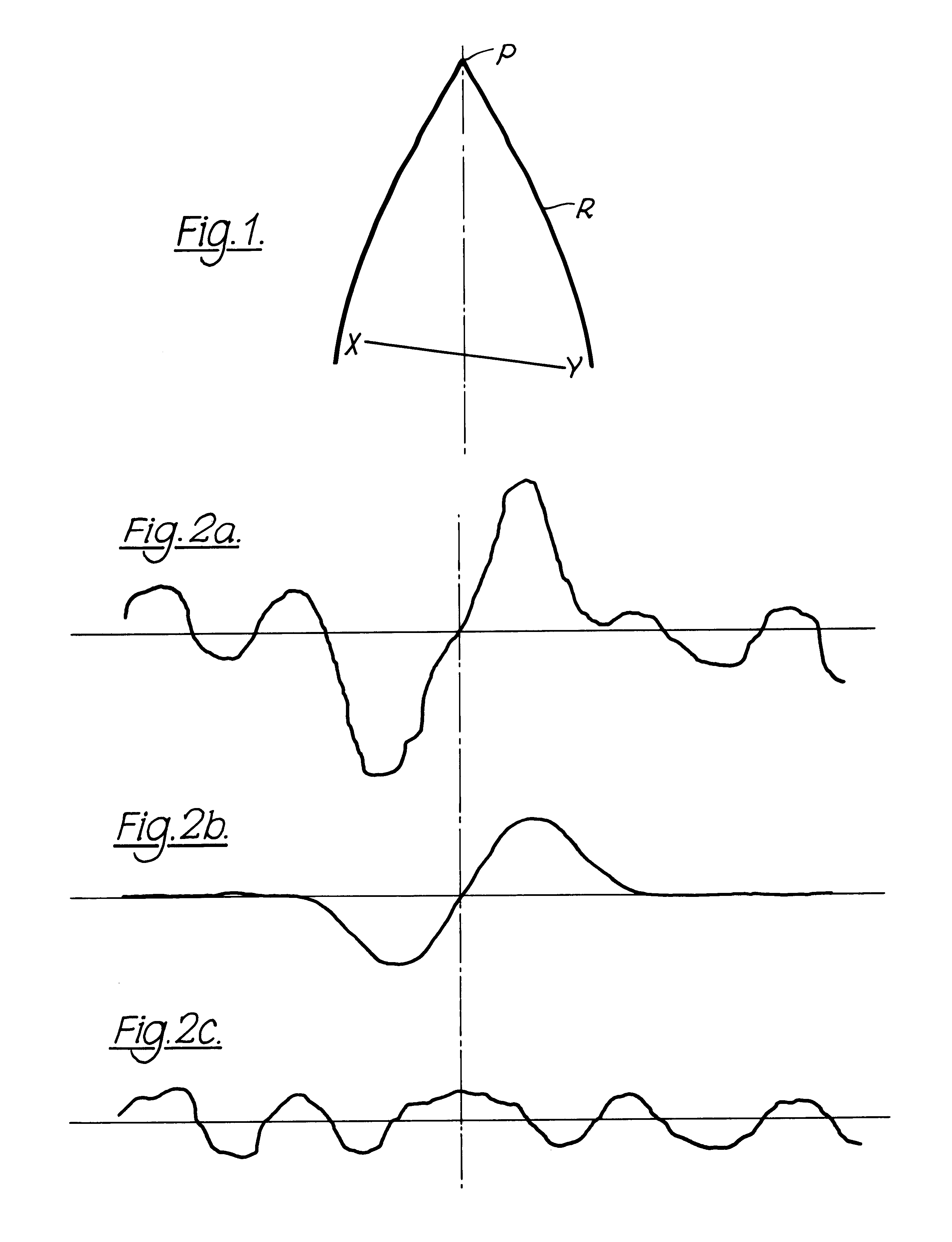
[0021]Referring to the drawings, FIG. 1 shows a steerable antenna XY, which may be of slotted plate form, enclosed in the radome R. As the boresight of the antenna is steered from side to side in tracking the target there is an aberration between the true line of sight to the target and the antenna boresight.

[0022]This aberration is illustrated in FIG. 2(a) in which the ordinate represents the error between the true line of sight and the apparent line of sight as indicated by the boresight. The sign of the error, positive or negative, indicates the direction of the error, left or right in azimuth.

[0023]The invention arises partially as a result of the realisation that the composite error diagram of FIG. 2(a) can in fact be analysed into two error components, one of which is largely independent of frequency and the other of which is strongly frequency dependent. It will be appreciated that the diagrams are for a single, say azimuth, plane, and that corresponding diagrams apply for th...


PUM


Abstract

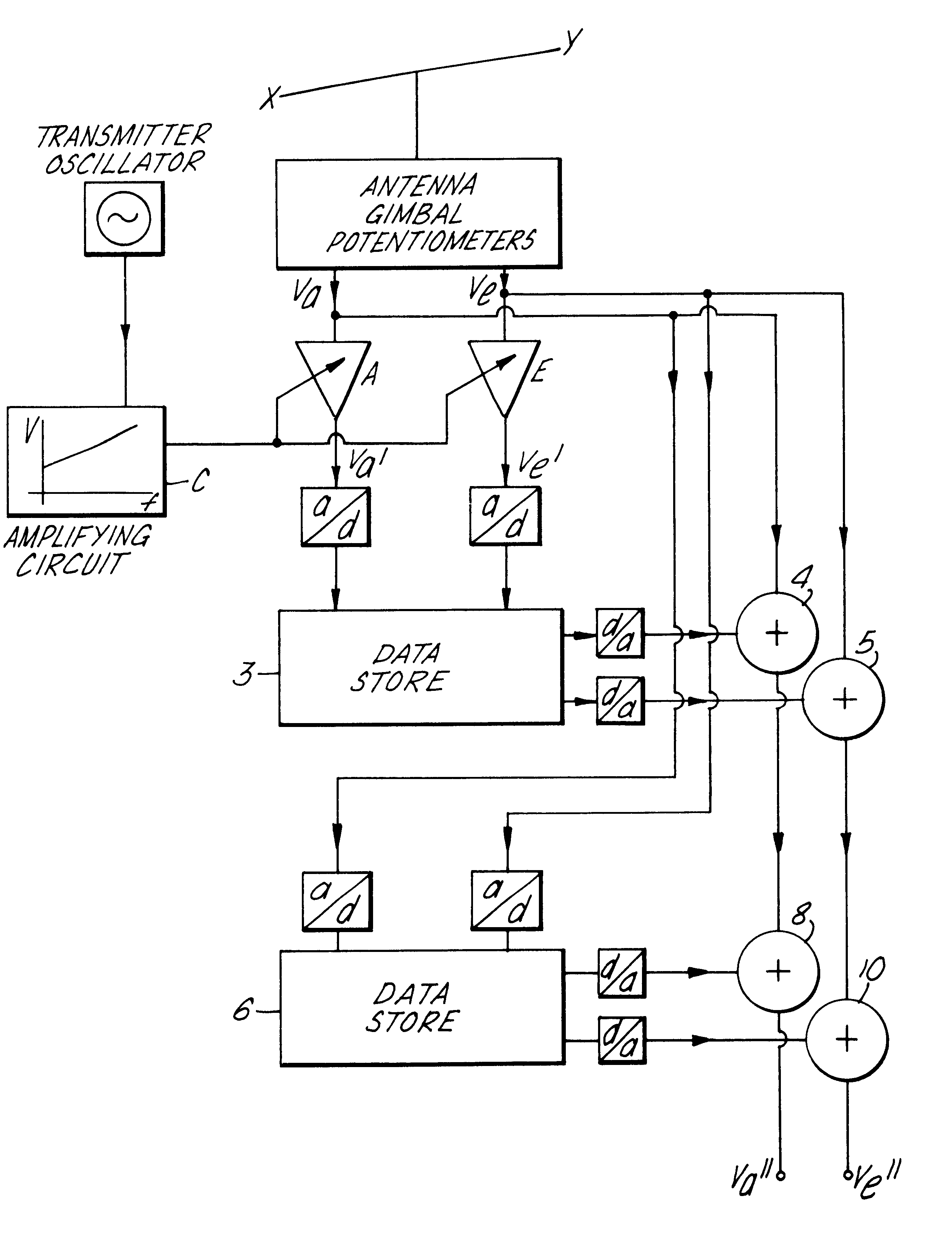
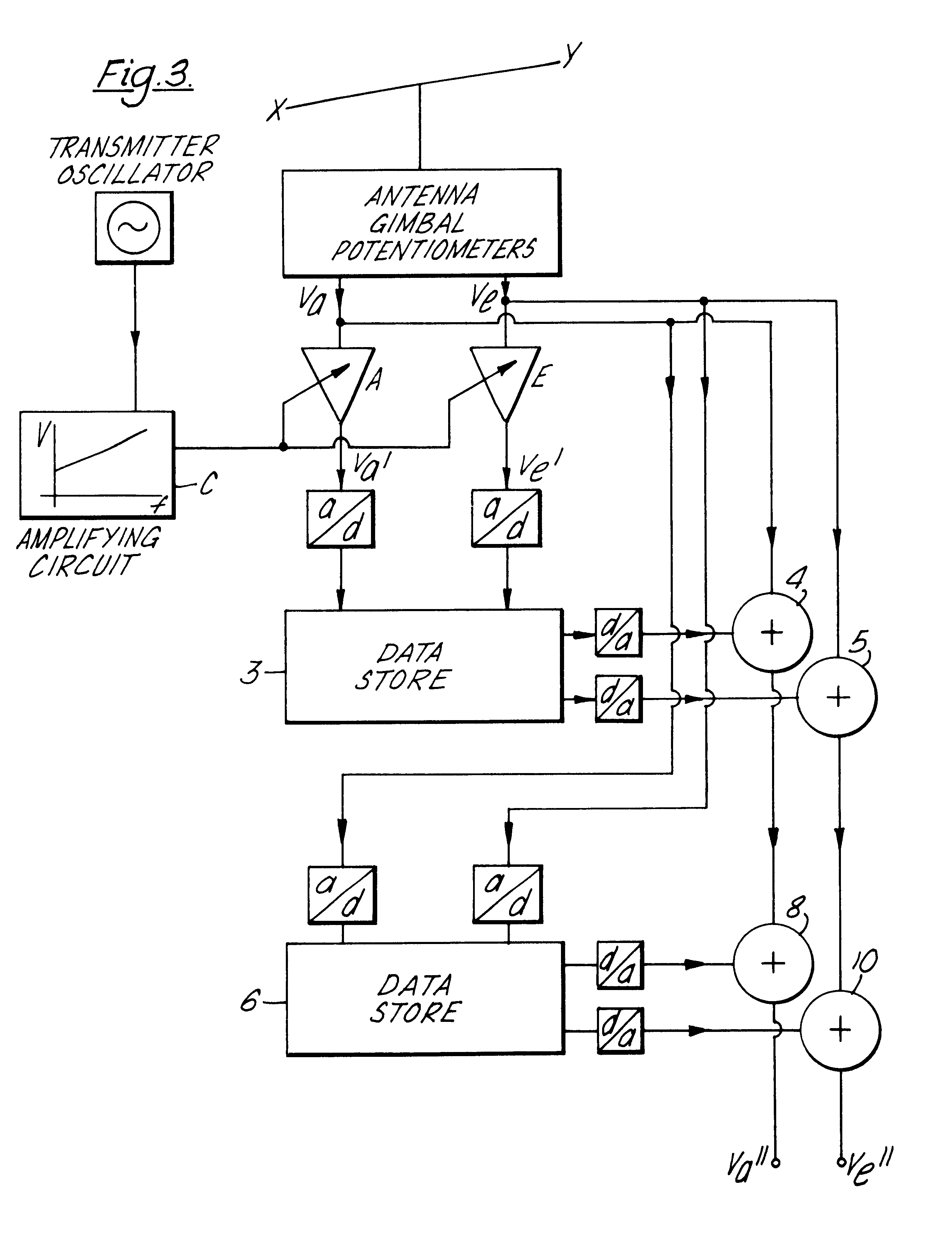
A system for correcting the effect of radome aberration on line-of-sight signals indicating target position. The aberration is in fact dependent upon both operating frequency and ‘angle-of-look’ and the essence of the present invention is to separate the corrections appropriate to each of these factors. The apparent line-of-sight signals are subjected to a frequency dependent amplification the result being used to address a store of error correction data. The apparent line of sight signals are also used to address a second store of error correction data and the two sets of correction data are added into the apparent line-of-sight signals to give true line-of-sight.

Description

CROSS REFERENCE TO RELATED APPLICATION[0001]This application is a continuation-in-part of application Ser. No. 06 / 054,148 filed Jun. 29, 1979 now abandoned.BACKGROUND OF THE INVENTION[0002]This invention relates to a radome aberration correcting system, particularly, although not exclusively, for use in a target tracking missile.[0003]It is known that the effect of a radome between a steerable antenna and a target gives rise to errors in the derivation of the target line of sight. It has previously been proposed to correct such aberration by adjusting the thickness of the radome locally for a range of target directions relative to the radome. Such a procedure is very tedious and time consuming since the radome is commonly made of refractory ceramic material which has to be ground to adjust its contour.[0004]Another proposal for correcting radome aberration is- to-store the line of sight errors for a range of target directions and to make the appropriate correction according to the a...

Claims


Application Information

Patent Timeline
Patent Type & Authority Patents(United States)
IPC IPC(8): G01S7/00G01S7/40H01Q1/42
CPCG01S7/4026H01Q1/42G01S2007/4034G01S2007/403G01S7/403G01S7/4034
Inventor PRICE, JOHN CLIFFORDMOORE, TREVOR STANLEY
Owner ALENIA MARCONI SYSTEMS
Why Eureka
Try Eureka