Solar light hub and router device

a solar light hub and router technology, applied in the direction of solar-ray concentration, photovoltaics, heat collector mounting/support, etc., can solve the problems of deterioration of various exposed surfaces, affecting the operation of such components, and important limitations in the performance of devices, so as to reduce the cost and complexity of control systems, reduce the cost and complexity of solar thermal energy plants, and facilitate and precision

Active Publication Date: 2018-02-22
VERTANESSIAN ALEJANDRO
View PDF1 Cites 1 Cited by
  • Summary
  • Abstract
  • Description
  • Claims
  • Application Information

AI Technical Summary

Benefits of technology

[0008]In order to overcome the structural and functional limitations and drawbacks of the known devices, such as the one disclosed and protected by the patent AR00764161, the device of the present invention has been developed, which brings together outstanding advantages that arise as a result of its compact structure design that allows the preservation of mirrors, lenses, and other components against the action of aggressive external factors, as well as the versatility of use for the use of solar energy. In fact, this device can be used both to direct concentrated solar rays to a tower where they are installed, for example, converter panels of solar energy into electrical energy, thermal, etc. as well as an autonomously way to take advantage of the energy of the solar rays concentrated by the device placing in the same device elements of photovoltaic, photochemical, thermo mechanical conversion among others possible; the focus of the solar rays is realized with greater facility and precision than in the case of the conventional heliostats, in which the cost and the complexity of the control system are reduced remarkably; the energy receiver / converter elements of the solar rays concentrated by the device can be installed at a relatively low height, so high-rise towers are not required; the use of a large number of these devices considerably reduces the cost and complexity of the solar thermal energy plants of the tower; by placing several devices on flat ground, they do not shade each other, so that it is not necessary that the receiver element(s) and energy converters provided by the concentrated solar rays are located at a high altitude in a tower, nor to separate the mirrors among themselves such as should be located in the case of heliostats; the space between the devices on the ground can be minimal, which is optimum to the use of the available surface; and power plants may occupy smaller areas than conventional plants for the same power generated. Unlike conventional heliostats, it is not necessary to construct a heavy and firm reflective structure that must move with great accuracy to accommodate the changing position of the sun, since in the present device the moving part is small, light, and moves in a very small area.

Problems solved by technology

One of the drawbacks of the device of the patent AR007641B1 lies in the fact that it is specifically intended for the water heating stored in a tank, which, at the present, constitutes an important limitation in the performance of the device.
On the other hand, the structure of the device, formed by a plurality of parts coupled or fixed to each other, is such as to leave excessively exposed to the environment the components intended to receive, reflect, and concentrate the solar rays for the use of the energy generated from the same.
Consequently, the operation of such components runs the risk of being affected by the accumulation of particles and / or the impact of rigid materials, which may deteriorate the various exposed surfaces.
In addition, the distribution of said components form a broad and expanded structure, whereby both the assembly of the parts of the device, and the disassembly thereof for the purpose of repairing and / or transporting them, may require special precautions, all of which affects an increase of the general costs until the installation and start-up of the device, among other disadvantages.

Method used


Image

  • Solar light hub and router device
  • Solar light hub and router device
  • Solar light hub and router device

Examples


Embodiment Construction

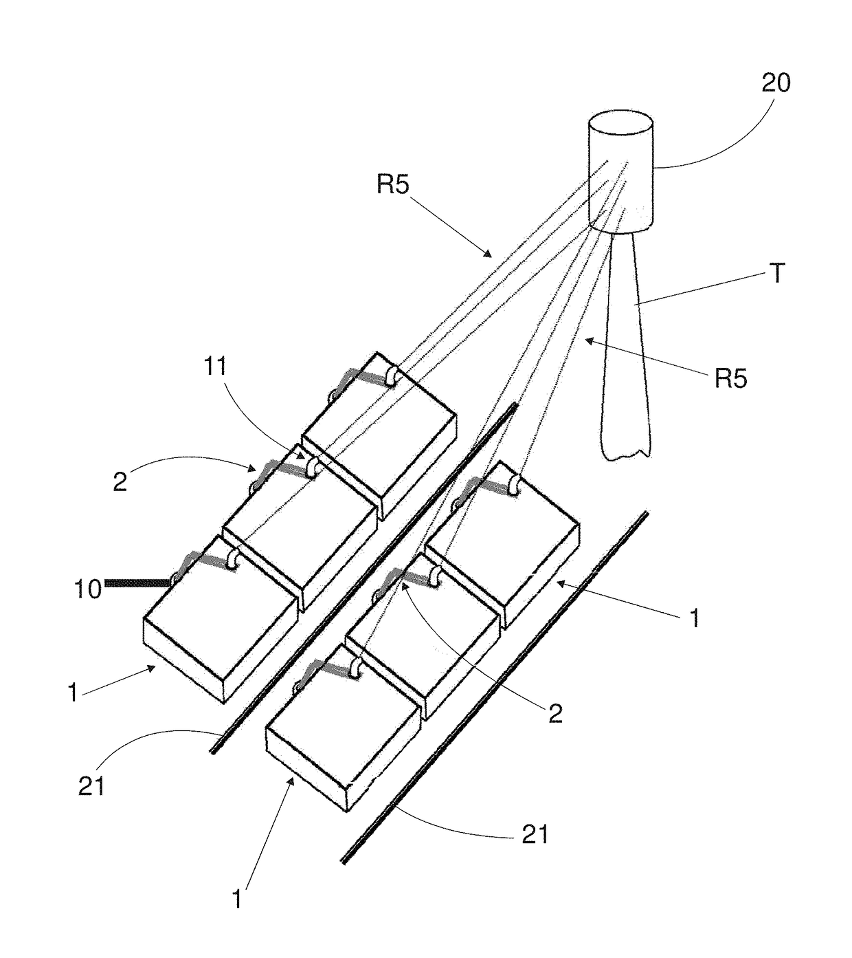
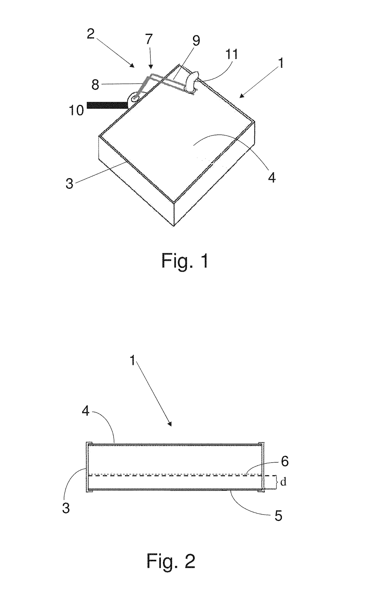
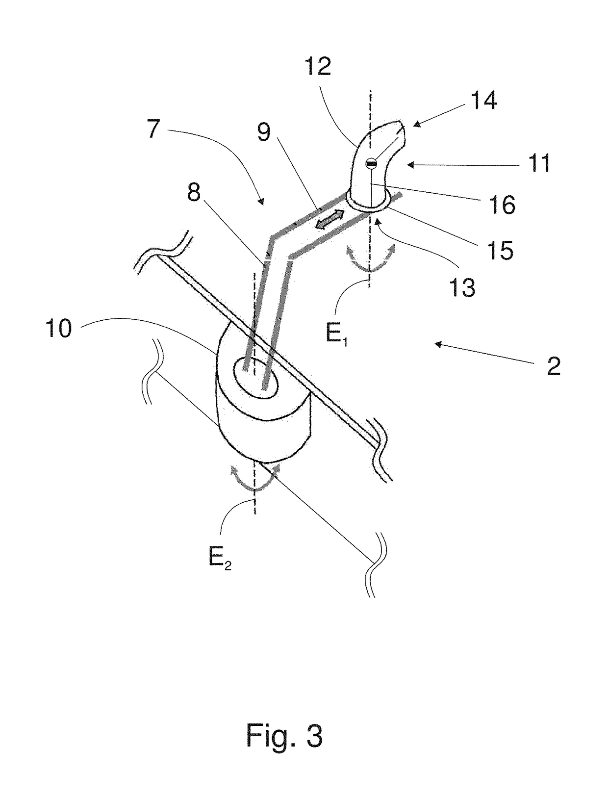
[0020]FIGS. 1 to 4 show the concentrator and solar energy router device of the present invention including a fixed body 1, which rests in a predetermined position on the floor or the ground where the device is installed, and a movable part 2 projecting from a perimetral section of the fixed body 1, which receives the concentrated solar rays emerging from the fixed body 1 in accordance with the changing positions of the sun in the course of the day and during different times of the year.

[0021]The fixed body 1 is formed by an outer frame 3, which can take various geometric configurations, for example, quadrangular as illustrated, but always with a flat top surface, and optionally may include support legs (not illustrated). The upper side of the fixed body 1 is defined by a plane-convergent lens 4, preferably a Fresnel-type lens, while on the bottom side or base includes a mirror 5. The lens 4 and the mirror 5 are firmly fixed in position by half of the frame 3.

[0022]According to alter...


PUM


Abstract

A concentrator and a solar light router for converting light energy into electrical, photochemical and thermal energy, among other possible forms of usable energy, comprising a fixed body (1) and a movable part (2), wherein the fixed body (1) has an upper side with a converging lens (4) through which the sun rays (R1) enter, and a lower side where a mirror (5) is arranged. The mobile part 2 has a support arm 7 having a lower leg 8 coupled to a movement unit 10, and an upper leg 9 extending above the converging lens 4, in which is displaceable mounted a module (11) receptor / router of convergent solar rays (R4) that emerges from the fixed body (1). The support (7) is connected to angular displacement means housed in the movement unit (10) so that the angle traveled by its arm (9) encompasses a virtual surface (17), defined between the converging lens (4) and the module (11), where a focal point (19) incise of the convergent rays (R4), that travels according to the curvilinear paths (18n) in accordance with the displacement of the sunlight captured by the converging lens (4). The module (11) presents a lower face (13) through which the converging solar rays (R4) enters, and an upper face (14) from which concentrated solar rays (R5) are emitted which are directed, for example, towards a solar energy converter receiver (20) arranged in a tower (T) spaced from the device. The module (11) is connected to translation means along the upper section (9) of the support (7) and to rotating means with respect to its axis (E1) transverse to the defined plane by the converging lens (4) and includes means detecting the positions of the focal point (19), which together with the angular arm displacement means (7) and the translational and rotational means of the module (11) are connected to a module position control and control unit (11) to maintain it facing the focal point (19) and facing the receiver / solar energy converter (20) of the tower (T). In an alternate realization, the module (11) may act as a solar energy receiver / converter, for which it may include solar cells, a thermoelectric motor, or other solar energy converters.

Description

FIELD OF THE INVENTION[0001]The present invention refers to a concentrator and router solar light device, and more particularly, a specially developed device to concentrate and direct the sunlight to exploit and use its energy for various purposes, which may be, for example, installed as a replacement of the conventional heliostats in a solar thermal plant of concentration in the top of a tower, utilized autonomously to take advantage of the solar rays energy concentrated by the device, placing on it, photovoltaic conversion elements, photochemical, thermo mechanical, among other possible options.STATE OF THE ART[0002]As a prior art in the field, it is worth it to mention, for example, patent AR00764161, which claim priority of the NZ 286.894 of Thomas James Finnie, and the application AR090573A1 claiming priority over application IT RM2012A000135 of Magaldi Industries S.R.L.[0003]The patent AR007641B1 protects a solar tracker and a solar energy collector capable of following the su...

Claims


Application Information

Patent Timeline
Patent Type & Authority Applications(United States)
IPC IPC(8): H02S40/22G02B19/00F24J2/08F24J2/38F24J2/40F24S23/70
CPCH02S40/22G02B19/0028G02B19/0042F24J2/08F24J2/38F24J2/40F24J2002/5273F24S23/00F24S23/31F24S23/70F24S50/20G02B3/08G02B19/0076Y02E10/44Y02E10/47Y02E10/52F24S23/30F24S50/00F24S2025/01
Inventor VERTANESSIAN, ALEJANDRO
Owner VERTANESSIAN ALEJANDRO
Why Eureka
Try Eureka