Method for increasing the signal-to-noise in IR-based eye gaze trackers

a technology signal-to-noise, which is applied in the field of eye gaze tracker, can solve problems such as inability to solve, and achieve the effect of reducing ambient ir nois

Inactive Publication Date: 2005-10-25
TOBII TECH AB
View PDF5 Cites 62 Cited by
  • Summary
  • Abstract
  • Description
  • Claims
  • Application Information

AI Technical Summary

Benefits of technology

[0010]The invention modulates the intensity of the illuminator with respect to time so that the illuminator signal may be extracted from the nearly constant ambient infrared radiation. The modulation of the illuminator is synchronized with the control of the camera / digitizing system to eliminate the need for pixel by pixel demodulation circuits. Several embodiments are disclosed for extracting the ambient IR (i.e., the noise) from the IR signal. In the first embodiment, the modulation of the IR illuminator is synchronized with each frame of the camera such that the illuminator alternates between on and off with each subsequent frame. A video frame grabber digitizes and captures each frame. If one considers a sequence of such frames, then the image captured in the first frame contains both the illuminator signal and the ambient radiation information. The image captured in the second frame contains only the ambient radiation information. By subtracting, pixel-by-pixel, the second frame from the first frame, a new image is formed that contains only the information from the illuminator signal. The resulting image can then be used by the conventional eye tracker system to compute the direction of eye gaze even in the presence of an ambient IR source. Other embodiments or variations are also disclosed for reducing ambient IR noise.

Problems solved by technology

However, this solution is not viable since increased IR radiation has associated health risks.

Method used


Image

  • Method for increasing the signal-to-noise in IR-based eye gaze trackers
  • Method for increasing the signal-to-noise in IR-based eye gaze trackers
  • Method for increasing the signal-to-noise in IR-based eye gaze trackers

Examples


first embodiment

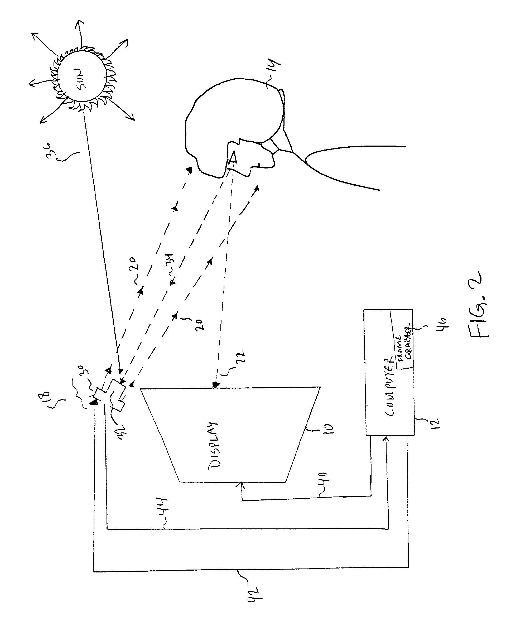
[0023]the present invention, exploits the observation that the intensity of sunlight and its constituent wavelengths of light, such as infrared radiation, do not vary rapidly. During the inter-frame interval of the camera 32 (typically 1 / 30th of a second), the level of ambient infrared radiation can be considered nearly constant. Therefore, the computer modulates the intensity of the illuminator 30 with respect to time. In this case, the modulation of the illuminator signal 42 is synchronized with each frame of the camera 32 such that the illuminator 30 alternates between on and off with each subsequent frame. A video frame grabber 46 digitizes and captures each frame. If one considers a sequence of such frames, then the image captured in the first frame contains both the illuminator signal and the ambient radiation information. The image captured in the second frame contains only the ambient radiation information. By subtracting, pixel-by-pixel, the second frame from the first fram...

third embodiment

[0030]As shown in FIG. 5, in the third embodiment, the computer synchronizes the illuminator 30 with the even and odd horizontal pixels. For example, the illuminator would be on for all even numbered horizontal pixels and off for the odd numbered horizontal pixels. This would effectively form alternating vertical stripes consisting of signal and noise or just noise information. The illuminator signal would be extracted by subtracting adjacent pixels from each other and taking the absolute value. Naturally, this modulation scheme would require an illuminator 30 capable of turning on and off many hundreds of times faster than required for the other schemes. This approach could be used with frames or fields.

[0031]As shown in FIG. 6, the second and third modulation techniques shown in FIGS. 4 and 5 can also be combined to yield a checkerboard pattern of noise pixels and signal plus noise pixels with adjacent pixels being subtracted to yield a reflection signal having improved S / N charac...


PUM


Abstract

The accuracy of eye gaze trackers is used in the presence of ambient light, such as sunlight, is improved. The intensity of sunlight and its constituent wavelengths of light, such as infrared radiation, do not vary rapidly. During the inter-frame interval of video cameras (typically 1 / 30th of a second), the level of ambient infrared radiation can be considered nearly constant. In a first embodiment, the modulation of the IR illuminator is synchronized with each frame of the camera such that the illuminator alternates between on and off with each subsequent frame. If one considers a sequence of such frames, then the image captured in the first frame contains both the illuminator signal and the ambient radiation information. The image captured in the second frame contains only the ambient radiation information. By subtracting the second frame from the first frame, a new image is formed that contains only the information from the illuminator signal. The resulting image can then be used by the conventional eye tracker system to compute the direction of eye gaze even in the presence of an ambient IR source.

Description

BACKGROUND OF THE INVENTION[0001]1. Field of the Invention[0002]The present invention generally relates to eye gaze trackers and, more particularly, to techniques for improving accuracy degraded by ambient light noise while maintaining safe IR levels output by the illuminator.[0003]2. Description of the Related Art[0004]The purpose of eye gaze trackers, also called eye trackers, is to determine where an individual is looking. The primary use of the technology is as an input device for human-computer interaction. In such a capacity, eye trackers enable the computer to determine where on the computer screen the individual is looking. Since software controls the content of the display, it can correlate eye gaze information with the semantics of the program. This enables many different applications. For example, eye trackers can be used by disabled persons as the primary input device, replacing both the mouse and the keyboard. Eye trackers have been used for various types of research, s...

Claims


Application Information

Patent Timeline
Patent Type & Authority Patents(United States)
IPC IPC(8): G06K9/20G06V10/145
CPCG06K9/2036G06V10/145
Inventor PECK, CHARLES C.
Owner TOBII TECH AB
Why Eureka
Try Eureka