Multipurpose testing system for optical cross connect devices

a testing system and cross-connect technology, applied in the field of optical technology, can solve the problems of increasing exponentially the length of time needed for performing conventional cross-connect verification testing, laborious testing scheme, and requiring a significant amount of time to compl

Inactive Publication Date: 2005-10-25
CALIENT TECH
View PDF8 Cites 43 Cited by
  • Summary
  • Abstract
  • Description
  • Claims
  • Application Information

AI Technical Summary

Benefits of technology

[0018]According to a specific embodiment, the optical switch testing system of the present invention may be used to measure and verify selected characteristics associated with a device under test (DUT) or a system unde

Problems solved by technology

However, it will be appreciated that such a testing scheme is labor intensive, and may require a significant amount of time to complete.
Moreover, as the number of input fibers and output fibers increase, the length of time needed to perform conventional cross-connect verification testing increases exponentially,

Method used


Image

  • Multipurpose testing system for optical cross connect devices
  • Multipurpose testing system for optical cross connect devices
  • Multipurpose testing system for optical cross connect devices

Examples


Embodiment Construction

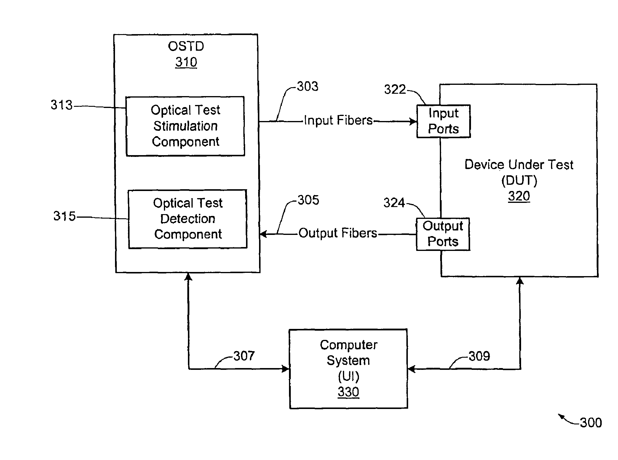
[0033]According to various aspects of the present invention, a novel optical switch testing system is described which provides a number of features and advantages not provided by conventional optical switch testing techniques. For example, as described in greater detail below, the optical switch testing system of the present invention may be used to quickly and economically test all desired optical paths which can be switched by an N×M optical switch. Additionally, the optical switch testing system of the present invention may also be used to measure and verify selected characteristics associated with a device under test (DUT) or a system under test (SUT). Such characteristics may include, for example, optical cross talk, insertion loss, polarization dependent loss, switching time, data integrity, optical path stability (e.g. path fluctuations over time, adjacent path setup / tear down interference, etc.), etc.

[0034]According to a specific embodiment, the optical switch testing system...


PUM


Abstract

A technique is disclosed for performing testing of an optical device under test (DUT). According to a specific embodiment, the DUT includes a plurality of DUT optical input ports and a plurality of DUT optical output ports. The testing may be performed by an optical switching testing system (OSTS) which includes a plurality of OSTS output ports optically connected to a plurality of DUT input ports, and a plurality of OSTS input ports optically connected to a plurality of DUT output ports. Components of the OSTS are configured in order to perform a specific test on the DUT. A first test scenario is configured at the DUT. At least one optical test signal is transmitted to at least one DUT input port. Test results may then be obtained by monitoring at least one DUT output port for the presence or absence of light. The test results are then analyzed for specific characteristics. According to a specific embodiment, the OSTS of the present invention may be adapted to automatically perform a plurality of testing operations on a selected plurality of different optical paths associated with the DUT. Such testing operations may include, for example, transmitting a plurality of optical test signals to a plurality of DUT input ports during a given test scenario, and/or monitoring a plurality of DUT output ports for test results during a given test scenario. According to a specific embodiment, the optical switch testing system of the present invention may be used to measure and verify selected characteristics associated with a device under test (DUT) or a system under test (SUT). Such characteristics may include, for example, optical cross talk, insertion loss, polarization dependent loss, path switching time, data integrity, optical path verification, optical path stability, etc.

Description

RELATED APPLICATION DATA[0001]The present application related to U.S. patent application No. 09 / 548,587 for “FEEDBACK STABILIZATION OF A LOSS OPTIMIZED SWITCH” by John Bowers filed on Apr. 13, 2000, the entirety of which is incorporated herein by reference for all purposes.[0002]The present application is also related to U.S. patent application No. 09 / 805,528 for “AN OPTICAL SWITCH WITH INTERNAL MONITORING” by David Edward Welsh, Roger Jonathan Helkey, Adrian Keating, Daniel J. Blumenthal, and Walter Joseph Fant, filed on Mar. 12, 2001, the entirety of which is incorporated herein by reference for all purposes.[0003]The present application is also related to U.S. patent application No. 09 / 854,265 for “PERFORMANCE MONITORING IN MULTI-STAGE SWITCHES” by Dan Blumenthal, Walt Fant, Roger Jonathan Helkey, and Charles Corbalis, filed on May 10, 2001, the entirety of which is incorporated herein by reference for all purposes.[0004]The present invention is also related to U.S. patent applic...

Claims


Application Information

Patent Timeline
IPC IPC(8): G02B6/26G02B6/42G01M11/00
CPCG01M11/335G01M11/337
Inventor LOFLAND, ROBWHITE, KEVINAGRAWAL, KAUSHAL K.HUNT, PETER
Owner CALIENT TECH
Why Eureka
Try Eureka