
Vehicle control apparatus

a technology for controlling apparatus and vehicles, applied in mechanical apparatus, instruments, transportation and packaging, etc., can solve the problems of causing inability to generate desired driving force, etc., to reduce time lag, reduce the risk of causing a delay in building up a driving force, and improve the effect of respons

Inactive Publication Date: 2005-10-25
HONDA MOTOR CO LTD
View PDF6 Cites 21 Cited by
  • Summary
  • Abstract
  • Description
  • Claims
  • Application Information

AI Technical Summary

Benefits of technology

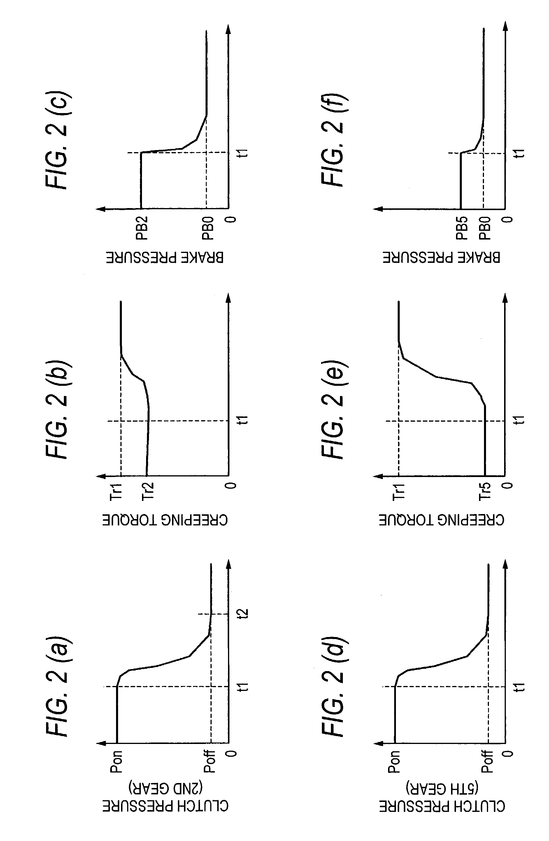
[0013]According to the vehicle control apparatus constructed as described above, the operating condition detecting unit has detected the operating condition of the braking unit operated by the driver when the internal combustion engine is stopped, and the connecting and disconnecting unit changes gear ratios of the transmission in stepped fashion according to the detected operating condition, whereby an appropriate driving torque can be generated according to the braking operation by the driver when the internal combustion engine is started to thereby prevent the generation of excessive so-called creeping torque that would be accompanied by the start of the internal combustion engine. Moreover, the high-speed gear is prevented from being selected excessively when the vehicle is started to thereby restrain the time lag required for selecting and changing gears, thereby making it possible to generate quickly a desired driving torque.
[0015]According to the vehicle control apparatus constructed as described above, in the event that the operating amount of the braking unit is relatively large, the relatively low-speed side change-speed gear is selected, whereby the response can be improved when the vehicle is started. In addition, in the event that the operating amount of the braking unit is relatively small, the relatively high-speed side change-speed gear is selected, whereby the generation of excessive so-called creeping torque can be prevented which would be accompanied by the start of the internal combustion engine.
[0016]Thus, an appropriate gear can be selected according to the braking operation by the driver, and the high-speed gear is prevented from being selected excessively when the vehicle is started to thereby restrain a time lag required for selecting and changing the gears, whereby a desired driving torque can quickly be generated.
[0020]According to the vehicle control apparatus constructed as described above, the shift control apparatus can ensure the operation of the connecting and disconnecting unit by activating the electric oil pump even in the event that the discharge pressure of a mechanical oil pump driven by the internal combustion engine is lowered, for example, when the internal combustion engine comes to a stop.
[0022]According to the vehicle control apparatus constructed as described above, in the event that the operating amount of the braking unit is relatively large, the low gear or the second gear is selected so that the high-speed gear is prevented from being selected excessively to thereby restrain the time lag required for selecting and changing the gears, whereby a desired driving torque can be generated quickly, thereby making it possible to improve the response when the vehicle is started from rest.

Problems solved by technology

Incidentally, with the above prior art automatic engine stop and start apparatus in which a high-speed gear of the automatic transmission is set to be selected when the engine is started, for example, even in case the driver wants a quick start, there may be a risk of causing a delay in building up a driving force.
Namely, when the driver starts the vehicle after he or she has released the brake there may be a case where a desired driving force cannot be generated at an appropriate timing due to a time lag required when the gears of the automatic transmission are changed from the high-speed gear to the low-speed gear.

Method used


Image

  • Vehicle control apparatus
  • Vehicle control apparatus
  • Vehicle control apparatus

Examples


Embodiment Construction

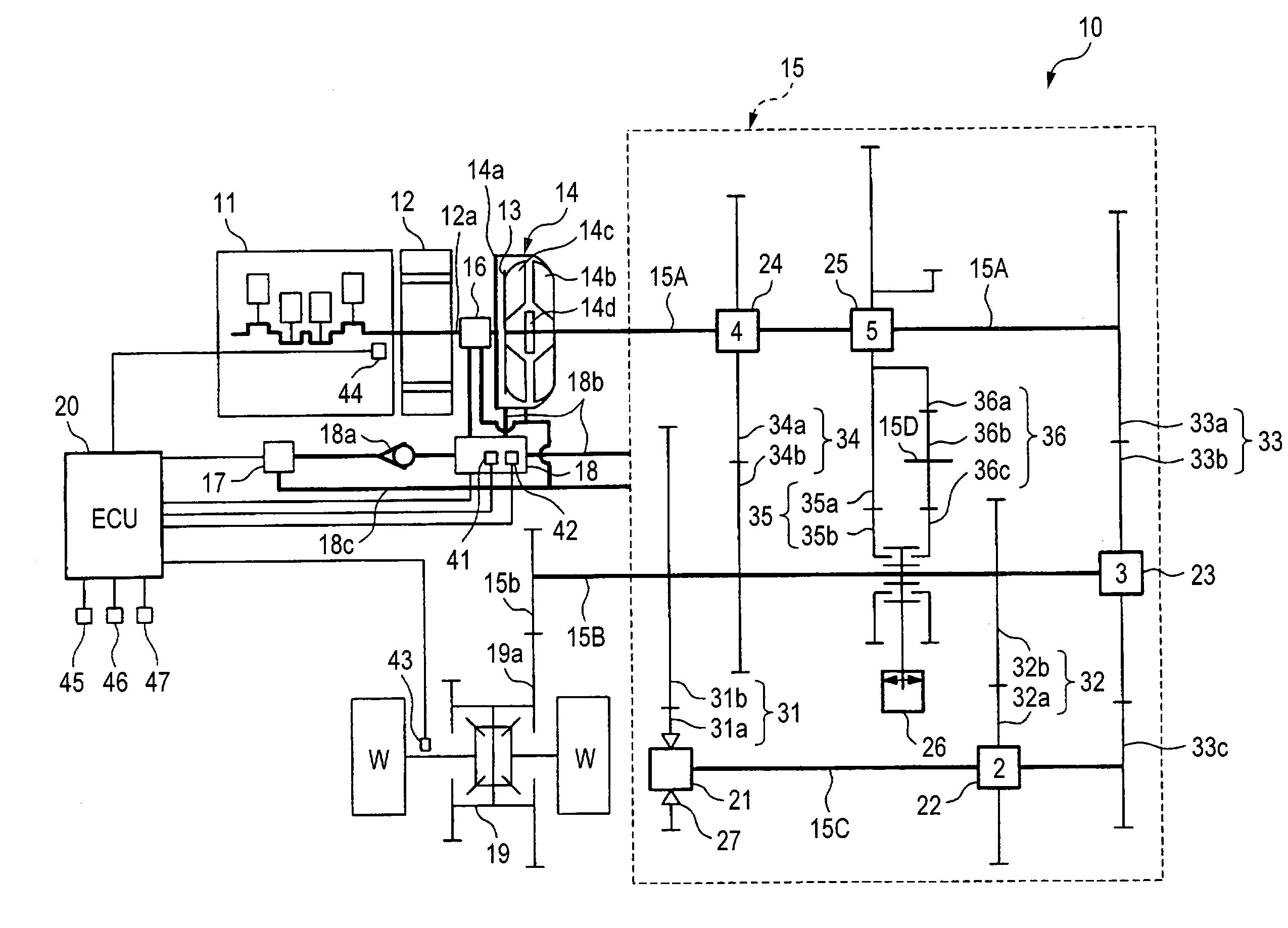
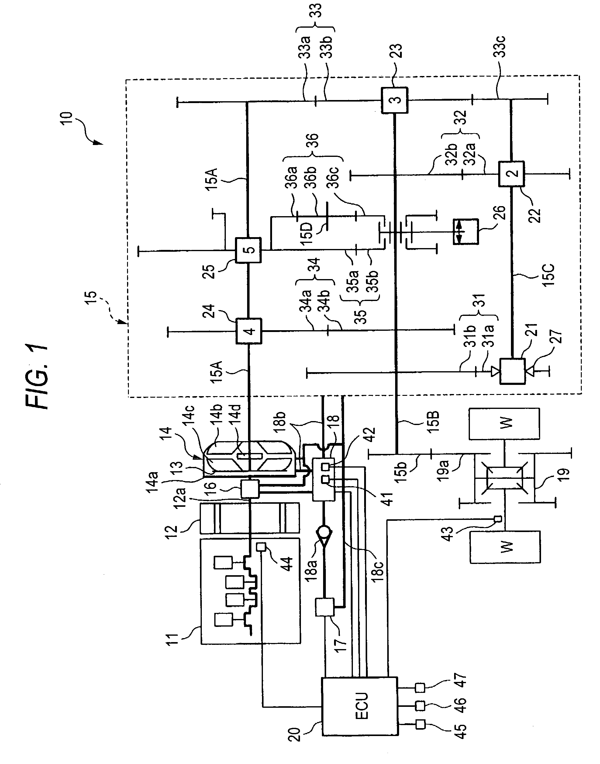
[0025]Referring to the accompanying drawings, a vehicle control apparatus according to an embodiment of the invention will be described below.

[0026]FIG. 1 is a diagram showing the construction of a main part of a hybrid vehicle having a vehicle control apparatus 10 according an embodiment of the invention.

[0027]The vehicle control apparatus 10 according to the embodiment is such as to transmit the driving force of at least either of an internal combustion engine 11 and a motor 12 to driving wheels W, W of a vehicle via a torque converter 14 and a transmission 15. The vehicle control apparatus 10 includes the internal combustion engine 11 and the motor 12 which are directly connected to each other in series, the torque converter 14 connected to a rotational shaft 12a of the motor 12, the transmission 15, a mechanical oil pump 16 and an electric oil pump 17 which generate oil pressures for controlling the driving of the torque converter 14 and the transmission 15, an oil pressure supp...


PUM


Abstract

A vehicle control apparatus generates an appropriate driving force according to the will of a driver when an internal combustion engine is restarted from a condition in which the idling of the engine is being stopped. In a condition in which the idling of an internal combustion engine 11 is being stopped, in the event that the depressing amount of a brake pedal by the driver is relatively large, an ECU (20) selects a relatively low-speed side gear of a transmission (15) so as to connect an input shaft (15A) and an output shaft (15B) together, and in contrast, in the event that the depressing amount of the brake pedal by the driver is relatively small, the ECU (20) selects a relatively high-speed side gear of the transmission (15) so as to connect the input shaft (15A) and the output shaft (15B) together.

Description

BACKGROUND OF THE INVENTION[0001]1. Field of the Invention[0002]The present invention relates to a vehicle control apparatus having an automatic transmission and adapted to stop the idling of an engine under a predetermined stop condition, and more particularly to a technology for controlling the operation of the automatic transmission when the idling of the engine is stopped.[0003]2. Description of the Related Art[0004]There have been known conventional automatic engine stop and start apparatuses, as with, for example, an automatic engine stop and start apparatus disclosed by JP-A-60-125738, which include an engine stop / start means for automatically stopping or starting an engine when a predetermined engine stop or start condition is met, a high-speed gear selecting means for selecting a high-speed gear of an automatic transmission when the engine is stopped, and a low-speed gear selecting means for selecting a low-speed gear of the automatic transmission after a predetermined leng...

Claims


Application Information

Patent Timeline
IPC IPC(8): B60K6/04B60K6/00F16H61/02B60W10/02F16H61/20B60W20/00F16H61/18F16H63/46
CPCB60K6/485B60W10/02B60W10/10B60W10/11B60W30/18018F16H61/0213F16H63/46B60K6/547Y10T477/688B60K2741/225B60L2240/441B60W20/00B60W2510/0638B60W2540/12F16H2061/023Y02T10/6226B60W30/1819Y02T10/62B60W10/06B60W20/30
Inventor MORISHITA, NAOHISAHAMADA, TETSUROUAOKI, TAKASHI
Owner HONDA MOTOR CO LTD
Learn More