Computer controlled engine valve operation

a computer controlled, engine technology, applied in the direction of electrical control, non-mechanical valves, ignition automatic control, etc., can solve the problems of degraded catalyst performance, tailpipe emissions, and disturbance of air-to-fuel mixture supplied to the subsequent cylinders, so as to reduce the error of exhaust air-fuel ratio and accurately maintain the overall exhaust gas air-fuel ratio

Inactive Publication Date: 2005-11-01
FORD GLOBAL TECH LLC
View PDF15 Cites 24 Cited by
  • Summary
  • Abstract
  • Description
  • Claims
  • Application Information

AI Technical Summary

Benefits of technology

[0005]In this way, it is possible to transition between early and late intake valve timing while reducing exhaust air-fuel ratio errors during the transition. In other words, by determining medium that

Problems solved by technology

However, the inventors herein have recognize a disadvantage with systems that transition valve timing between early intake valve closing (EIVC) and late intake valve closing (with valve closing past BDC (bottom dead center) (i.e., in the compression stroke).
In particular, the transition between early intake valve closing (EIVC) operation and late intake valve closing (LIVC) operation can be diff

Method used


Image

  • Computer controlled engine valve operation
  • Computer controlled engine valve operation
  • Computer controlled engine valve operation

Examples


Embodiment Construction

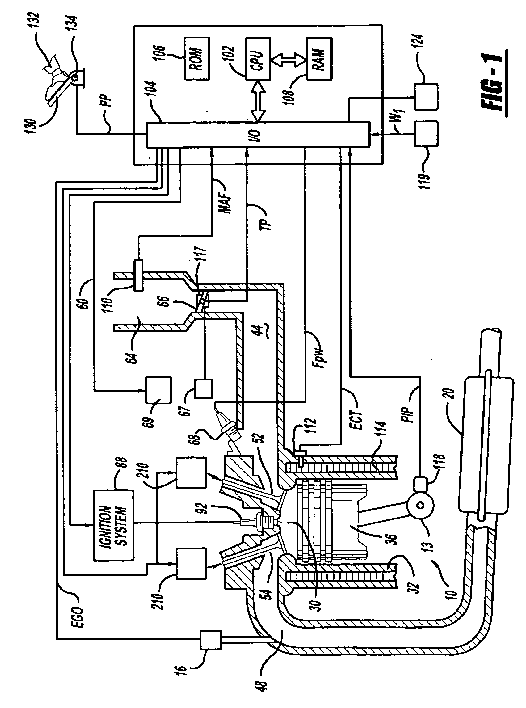
[0019]Referring to FIG. 1, internal combustion engine 10 is shown. Engine 10 is an engine of a passenger vehicle or truck driven on roads by drivers. Engine 10 is coupled to torque converter via crankshaft 13. The torque converter is also coupled to transmission via turbine shaft. The torque converter has a bypass clutch, which can be engaged, disengaged, or partially engaged. When the clutch is either disengaged or partially engaged, the torque converter is said to be in an unlocked state. The turbine shaft is also known as transmission input shaft. The transmission comprises an electronically controlled transmission with a plurality of selectable discrete gear ratios. The transmission also comprises various other gears such as, for example, a final drive ratio. The transmission is also coupled to tires via an axle. The tires interface the vehicle to the road.

[0020]Internal combustion engine 10 comprising a plurality of cylinders, one cylinder of which is shown in FIG. 1, is contro...


PUM


Abstract

An electronic valve actuation system and control method is described. The valve timing is changed between early and late intake valve closing depending on engine operating conditions. Further, valve timing is adjusted to control engine airflow or engine torque. Finally, air-fuel ratio is adjusted based on feedback from an exhaust gas oxygen sensor as well as an estimate of air, fuel, and residual exhausted from cylinders operating with late valve closing (after bottom dead center) timing.

Description

BACKGROUND OF THE INVENTION[0001]Engines of vehicles can operate with an emission control device to reduce exhaust emissions. In order to achieve efficient conversion of exhaust emissions, emission control devices such as catalytic converters require specific exhaust air-fuel ratios. Thus, fuel injection is typically controlled in order to provide a desired exhaust air-fuel ratio and thereby improve emission reduction.[0002]However, the inventors herein have recognize a disadvantage with systems that transition valve timing between early intake valve closing (EIVC) and late intake valve closing (with valve closing past BDC (bottom dead center) (i.e., in the compression stroke). In particular, the transition between early intake valve closing (EIVC) operation and late intake valve closing (LIVC) operation can be difficult to manage.[0003]For example, when the air-fuel charge starts to be pushed back into the intake manifold from the cylinder in late valve timing (due to compression f...

Claims


Application Information

Patent Timeline
IPC IPC(8): F02D41/00F02D13/02F02D37/00F02D37/02F02M25/07
CPCF02D13/0207F02D13/0234F02D41/0002F02D41/0062F02D13/0219F02D13/0253F02D13/0261F02D13/0269F02D37/02F02D2041/001F02D2250/18F02M25/0752F02M25/0754F02M25/0755Y02T10/142Y02T10/42Y02T10/47Y02T10/18F02M26/46F02M26/01F02M26/47Y02T10/12Y02T10/40
Inventor SONG, GANGKOLMANOVSKY, ILYA V.MICHELINI, JOHN OTTAVIOGIBSON, ALEXANDER O'CONNORHARDY, LARRY ALLENCULLEN, MICHAEL JOHNZHANG, XIAOYINGJANKOVIC, MRDJAN J.
Owner FORD GLOBAL TECH LLC
Why Eureka
Try Eureka