Baffle system for two-phase annular flow

a two-phase annular flow and blower technology, applied in fluid removal, earth-moving drilling, wellbore/well accessories, etc., can solve the problems of increasing the chance of the bubble reaching the pump, the pump ingesting gas, and the gas lock of the pump, so as to reduce the occurrence of pump gas lock, reduce the damage of the well, and reduce the effect of pressure fluctuations

Inactive Publication Date: 2005-11-01
PRESTON YALE MATTHEW
View PDF4 Cites 28 Cited by
  • Summary
  • Abstract
  • Description
  • Claims
  • Application Information

AI Technical Summary

Benefits of technology

[0016]The present invention is directed to apparatus and methods for mitigating well bore anomalies that may inhibit proper operation of production equipment. For example, pressure fluctuations may be reduced, thus reducing the occurrence of pump gas lock and reducing well bore damage caused by extreme pressure differentials across the comparatively soft structure of a coal seam. An apparatus made in accordance with one embodiment of the invention may include a well casing extending into the earth with an inlet positioned at a coal seam aquifer and an outlet positioned at the earth's surface. A well bore may be formed directly below the inlet of the well casing. Usually, a well bore is drilled into a coal seam aquifer, an may be partially or completely cased. If a bore is cased only to the top of the seam, then a substantially larger bore diameter (under ream) is typically cut below the cased bore for increasing available surface area for flow into the bore and to the pump. This under reamed region also acts as a cistern or collection location to buffer the flow of methane and water toward the pump and casing. As a practical matter, the under reamed region provides some amount of time in which gas may separate from water, for better or worse.
[0019]A water column manifests its presence by increasing the pressure on the well bore. Due to the dynamic nature of the ascending and descending of various slugs of water within the gas flow path, the pressure in the well bore may vary. High pressures within the well bore generate a significant impetus for gas bubbles in the well bore to find a location of lower pressure. Typically, the location of lowest pressure within the well bore is the pump inlet. Thus, a dynamic and heavy water column, trapping a large bubble of gas therebelow, subjects the bubble to a comparatively high pressure. This may increase the chance of that bubble reaching the pump and the pump ingesting gas to become gas locked.
[0020]A baffle placed within the gas flow path may mitigate the pressure dynamics caused by water slugs within the gas flow path. The baffle may also lower the well bore pressure by precluding the formation of a significant water column. A baffle may operate by preferentially permitting the flow of gas over the flow of water therethrough. The drag on water is higher than the drag on gas. Thus, gas may flow up the gas flow path while water tends to stay in the well bore where it may be efficiently pumped to surface. A baffle in accordance with the present invention may distinguish between the flow of gas and the flow of water based on the respective viscosities, densities, and inertia of gas and water.

Problems solved by technology

Problems may occur in certain high gas and water producing coal bed methane wells.
This may increase the chance of that bubble reaching the pump and the pump ingesting gas to become gas locked.

Method used


Image

  • Baffle system for two-phase annular flow
  • Baffle system for two-phase annular flow
  • Baffle system for two-phase annular flow

Examples


Embodiment Construction

[0050]It will be readily understood that the components of the present invention, as generally described and illustrated in the Figures herein, could be arranged and designed in a wide variety of different configurations. Thus, the following more detailed description of the embodiments of the systems and methods of the present invention, as represented in FIGS. 1 through 27, is not intended to limit the scope of the invention, as claimed, but is merely representative of the certain selected embodiments of the invention. The presently disclosed embodiments of the invention will be best understood by reference to the drawings, wherein like parts are designated by like numerals throughout.

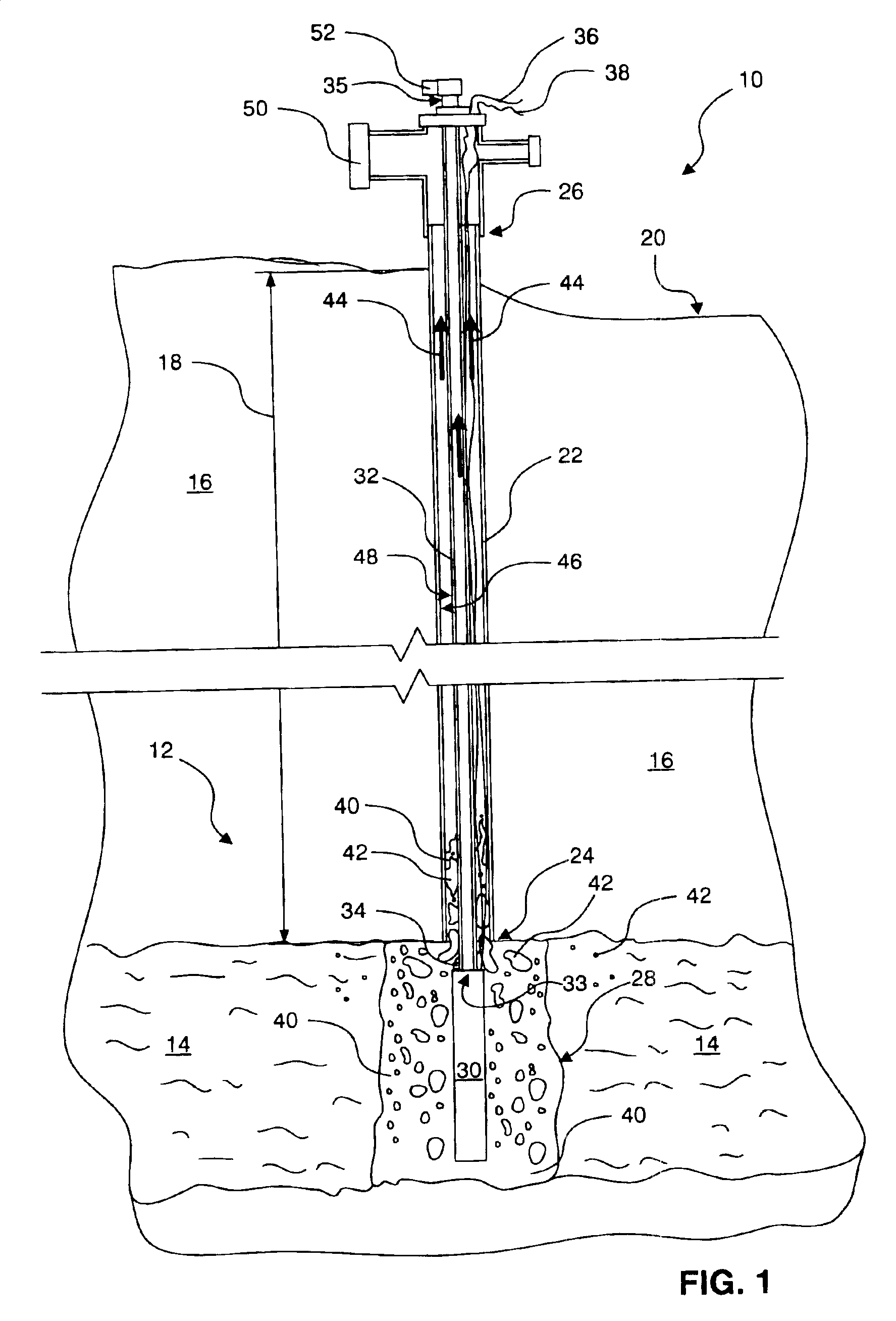
[0051]FIG. 1 illustrates a coal bed methane well 10 for extraction of methane (hereinafter gas). In describing the present invention, a coal bed methane well 10 will be used as an example of how the present invention, to be described in detail hereinbelow, may be applied. Those of skill in the art wil...


PUM


Abstract

An apparatus for promoting the flow of methane gas from a coal bed methane well. The apparatus may include a well casing extending into the earth to a cool seam aquifer. A conduit may be placed within the well and extend from the coal seam aquifer to the earth's surface. A pump may be connected to pump water from the coal seam aquifer through the conduit to the surface. A baffle may be placed in the gap formed between the interior surface of the well casing and the exterior surface of the conduit to the preferentially permit the flow of gas over the flow of water therethrough. The baffle may mitigate well bore pressure fluctuations, thus reducing the occurrence of pump gas lock and reducing well bore damage.

Description

BACKGROUND[0001]1. The Field of the Invention[0002]This invention relates to regulating two-phase flow and, more particularly, to novel systems and methods for optimizing production from wells such as those found in oil, gas, and coal bed methane fields.[0003]2. The Background Art[0004]The presence of methane (CH4, a principal ingredient of natural gas) in underground coal seams has long been known. In the past, coal bed methane was vented to provide a non-explosive, non-suffocating environment in which coal miners could work. However, in recent times, methane has become a popular fuel for use in electric generators, furnaces, city buses, and the like. Methane's popularity may largely be attributed to its relatively low cost and clean combustion characteristics. Meanwhile, conventional oil drilling and production is ongoing for petroleum and natural gas.[0005]Various techniques are used to collect coal bed methane. In recent development, water well technology is used to collect meth...

Claims


Application Information

Patent Timeline
Patent Type & Authority Patents(United States)
IPC IPC(8): E21B43/00E21B43/12E21B43/14
CPCE21B43/006E21B43/12E21B43/14
Inventor PRESTON, YALE MATTHEW
Owner PRESTON YALE MATTHEW
Why Eureka
Try Eureka