Method for selectively transferring at least an element from an initial support onto a final support

a technology of at least an element and a final support, applied in the direction of lasers, semiconductor laser structural details, sensors of record carriers, etc., can solve the problems of inability to make components on plastic supports, inability to achieve the growth of components with a great difference in link parameters (several hundred), and inability to use micro-electronic processes to make components. , to achieve the effect of limiting the losses of starting materials, and reducing the weight of these components

Inactive Publication Date: 2005-11-01
COMMISSARIAT A LENERGIE ATOMIQUE ET AUX ENERGIES ALTERNATIVES
View PDF14 Cites 25 Cited by
  • Summary
  • Abstract
  • Description
  • Claims
  • Application Information

AI Technical Summary

Benefits of technology

[0020]In addition, the invention enables us to associate a thin component on a support by using a joint by molecular adhesion that is compatible with the “front-end”. This allows us to treat the component after transfer with processes such as with high temperatures, for example. In this way, for example, we can resume an epitaxy or carry out the connections between the component and the support.
[0021]The transfer of labels also enables us to free ourselves from the differences in diameter between the substrates on which the components are made. This enables us, in particular, to limit the losses of starting material as compared with a full plate transfer where only certain zones transferred are used to make components.
[0023]In addition, the transfer of thinned components has the advantage of reducing the vertical obstruction, reducing the weights of these components and, furthermore, making them less fragile. But the transfer of thin layers or films is made difficult by their small size that makes them hard to handle. To facilitate that handling, it is advantageous to use a transfer support that is used as a rigidificator for the handling of these films, to avoid their bending out of shape under constraint, or even breaking. By rigidificator, we mean any organic or mineral support with a rigidity that prevents the breaking of pre-cut zones, allows the support of the set of chips and prevents splits and / or fractures and / or breakings of labels or elements to be transferred. That rigidificator can be, for example, a mono-crystalline silicon plate (001) with a minimum thickness of 200 μm. It can also be made of glass or any transparent material, for example in visible, infrared or ultraviolet. This, in particular, makes the alignment of the chip on the support possible. This also allows the treatment of the adhesion layer (for example: glue that can be hardened with ultraviolet rays).
[0024]The rigidificator used to transfer the labels can be a support commonly used in micro-electronics (mono-crystalline or poly-crystalline substrate, glass, etc.) or other supports such as plastic films sensitive to ultraviolet rays, double-face films, stretchable films, Teflon® films, etc. It can be a combination of these different supports allowing a better usage of the properties of each of them.
[0026]The purpose of the invention is also to provide an economical process to transfer components.
[0042]Before stage c), we could add to the transfer support, means enabling us to maintain that support rigid during stage c). After stage c), the means to rigidify the transfer support can be removed at least partially.

Problems solved by technology

It is obvious that the epitaxial growth of the components with a great difference in link parameters (several for hundreds) cannot be achieved with a quality that would prevent the degradation of their electrical and optical characteristics due to the presence of structural defects.
In another area, it is obvious that we cannot, with micro-electronic processes, make components on plastic supports, firstly, because the latter do not withstand the temperatures used and secondly, because they are not by nature, compatible with the cleanliness criteria of front-end stages in the semi-conductor industry.

Method used


Image

  • Method for selectively transferring at least an element from an initial support onto a final support
  • Method for selectively transferring at least an element from an initial support onto a final support
  • Method for selectively transferring at least an element from an initial support onto a final support

Examples


Embodiment Construction

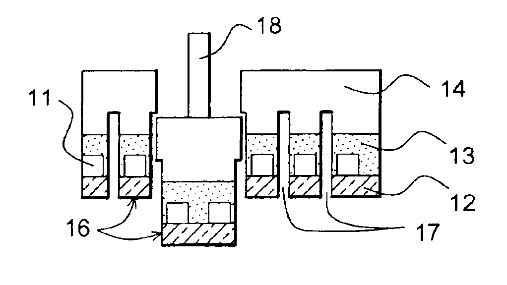
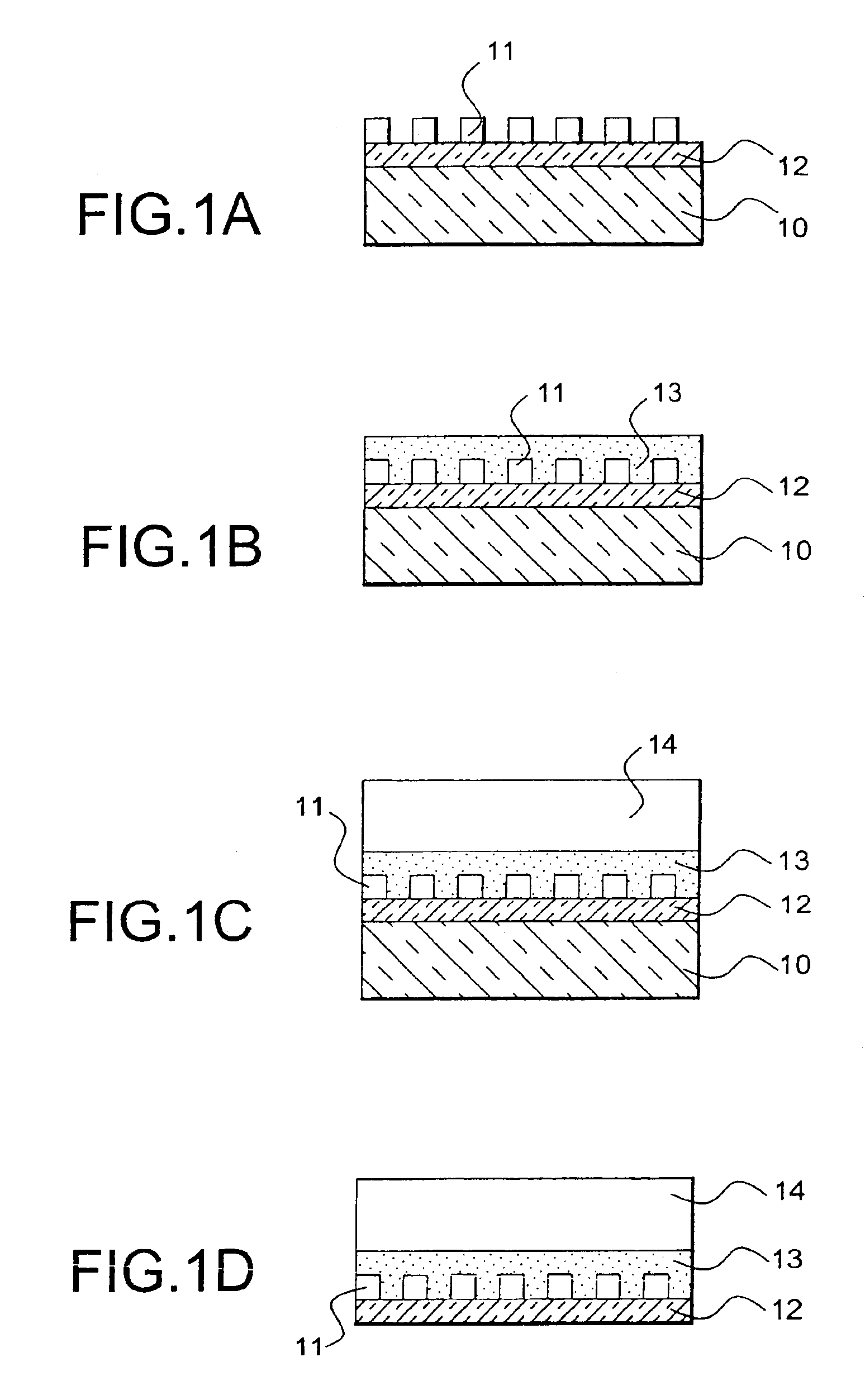
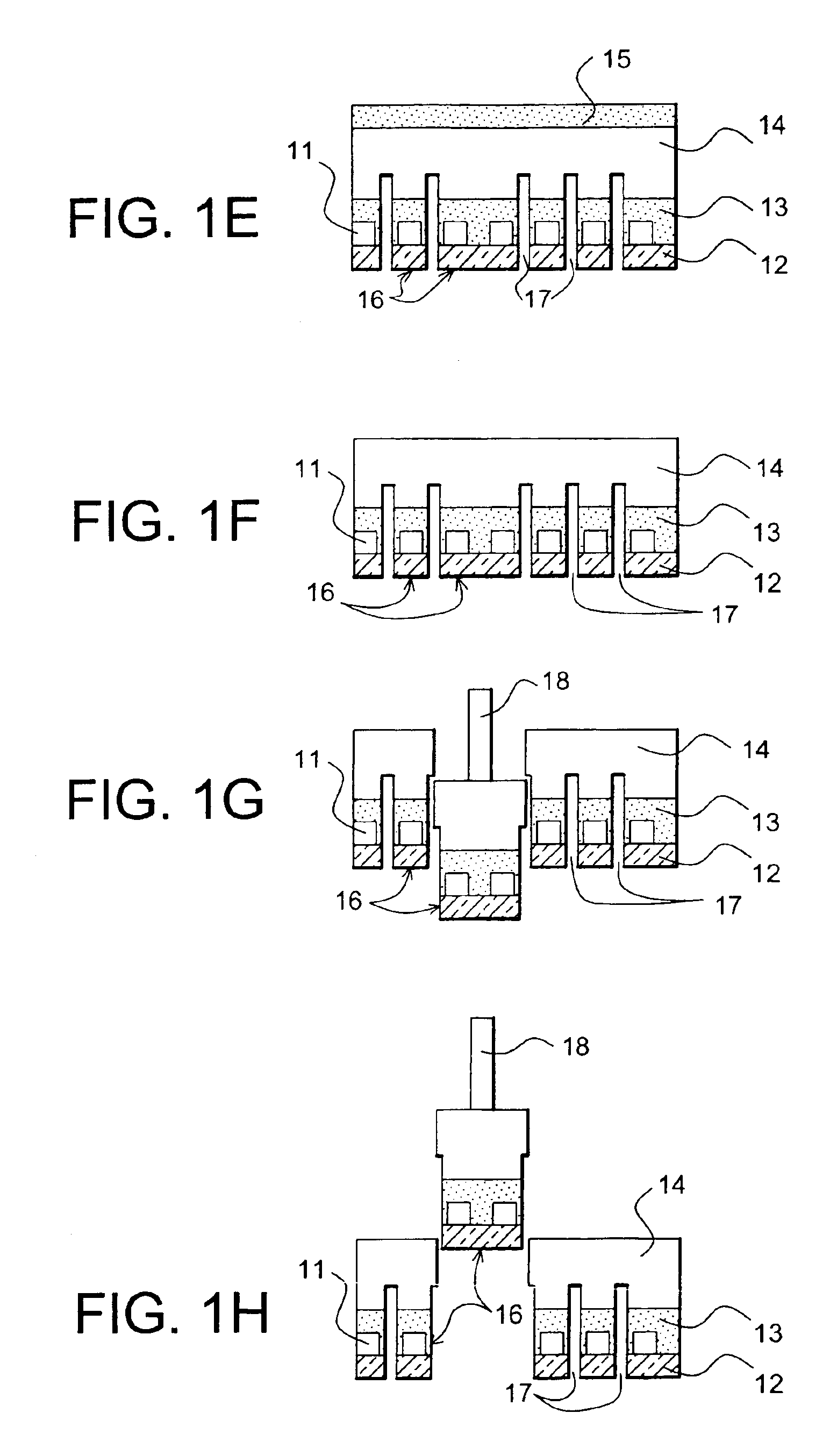
[0055]Generally speaking, the process applies to elements fully or partially made on substrates by the techniques of microelectronics and / or optoelectronics. The elements can possibly be made on one or several layers of chemical stoppage. They can possibly be subjected to an electric test on their initial support.

[0056]In case there exists a strong surface topology, a polishing of the surface can be carried out by the deposit of material followed by a chemical-mechanical polishing or by filling the volumes with a material sufficiently smooth that does not require any subsequent polishing. If the layer of filling material is sufficiently thick and rigid, it can also fulfil a function of rigidification and make up the transfer support. In addition, it can, when necessary, fulfil an adhesion function.

[0057]Different techniques can be used to fix the transfer support on the initial support: molecular adhesion, glue, epoxy resin, etc. The molecular adhesion is particularly appropriate wh...


PUM


Abstract

The invention concerns a process of selective transfer of labels from an initial support to a final support, each label including at least one element constituent of a microelectronic and / or optoelectronic and / or acoustic and / or mechanical device, with the elements made in a surface layer of the initial support, and the process including the following stages:a) Fixing a transfer support on the surface layer of the initial support;b) Eliminating the part of the initial support that does not correspond to the surface layer;c) Laterally defining the labels by cutting according to the thickness of the surface layer, with the cutting leaving zones to be broken off;d) Grasping one or several labels to be transferred and tearing them off by means of energy intake in the corresponding zones that can be broken off;e) Transfer and fixing the label or set of labels torn off in stage d) on the final support.

Description

BACKGROUND OF THE INVENTION[0001]1.—Field of the Invention[0002]The abovementioned invention concerns the selective transfer of one or several elements we can call labels, from a manufacturing support to a receiving support.[0003]It concerns, in particular, the transfer of semi-conducting chips, partially or fully completed, from their initial substrate on which they are manufactured to a new substrate (or receiving support) that can itself be treated by microelectronic techniques.[0004]The invention enables us, in particular, to transfer chips that may have been electronically tested, for example, chips of 1 mm2 to 1 cm2 area, from their initial substrate to a support made of treated or non-treated semi-conducting material, transparent material, (example: glass), a soft or rigid support (example: plastic) or a support made of ceramics. It also enables us, for example, to transfer optoelectronic components such as a vertical cavity surface emitting lasers or VCSEL or small pieces of...

Claims


Application Information

Patent Timeline
Patent Type & Authority Patents(United States)
IPC IPC(8): H01L21/67H01L21/68H01L21/70H01L21/98H01S5/00H01S5/02H01L21/02H01L21/52
CPCH01L21/6835H01L24/97H01L25/50H01L2221/68359H01L2221/68368H01L2224/83894H01L2924/01004H01L2924/01013H01L2924/01015H01L2924/01033H01L2924/01057H01L2924/01058H01L2924/01074H01L2924/01075H01L2924/01079H01L2924/01082H01L2924/01094H01L2924/09701H01L2924/10329H01L2924/19043H01L2924/30105H01S5/0201H01S5/0202H01S5/0215H01S5/0217H01L2924/01005H01L2924/01006H01L2924/01019H01L2924/01023H01L2924/01087H01L2924/10253H01L2924/00H01L2924/12042H01L21/68
Inventor FIGUET, CHRISTOPHEASPAR, BERNARDBLET, VINCENT
Owner COMMISSARIAT A LENERGIE ATOMIQUE ET AUX ENERGIES ALTERNATIVES
Why Eureka
Try Eureka