Injectable packing unit in a single knife gate body

a packing unit and knife gate technology, applied in the direction of valve details, valve arrangement, spindle sealing, etc., can solve the problems of time-consuming and expensive process for routine maintenance, undesirable leakage paths between body parts, etc., and achieve the effect of preventing leakag

Inactive Publication Date: 2005-11-01
ITT MFG ENTERPRISES LLC
View PDF39 Cites 24 Cited by
  • Summary
  • Abstract
  • Description
  • Claims
  • Application Information

AI Technical Summary

Benefits of technology

[0007]In accordance with a different feature of the invention, a knife gate valve according to this invention comprises a unitary valve body formed with a flow channel, a groove formed in and open to the flow channel, a knife gate seal carried in the groove and a knife gate carried in the valve body for movement between an open position and a closed position where in the knife gate seats against the seal to prevent leakage. Port liner guides are carried...

Problems solved by technology

However, the spacing between the body members provides undesirable leakage paths.
Moreover...

Method used


Image

  • Injectable packing unit in a single knife gate body
  • Injectable packing unit in a single knife gate body
  • Injectable packing unit in a single knife gate body

Examples


Embodiment Construction

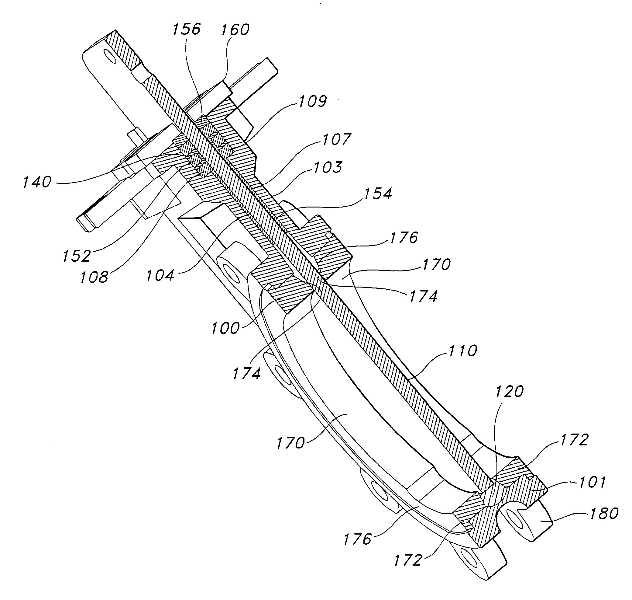
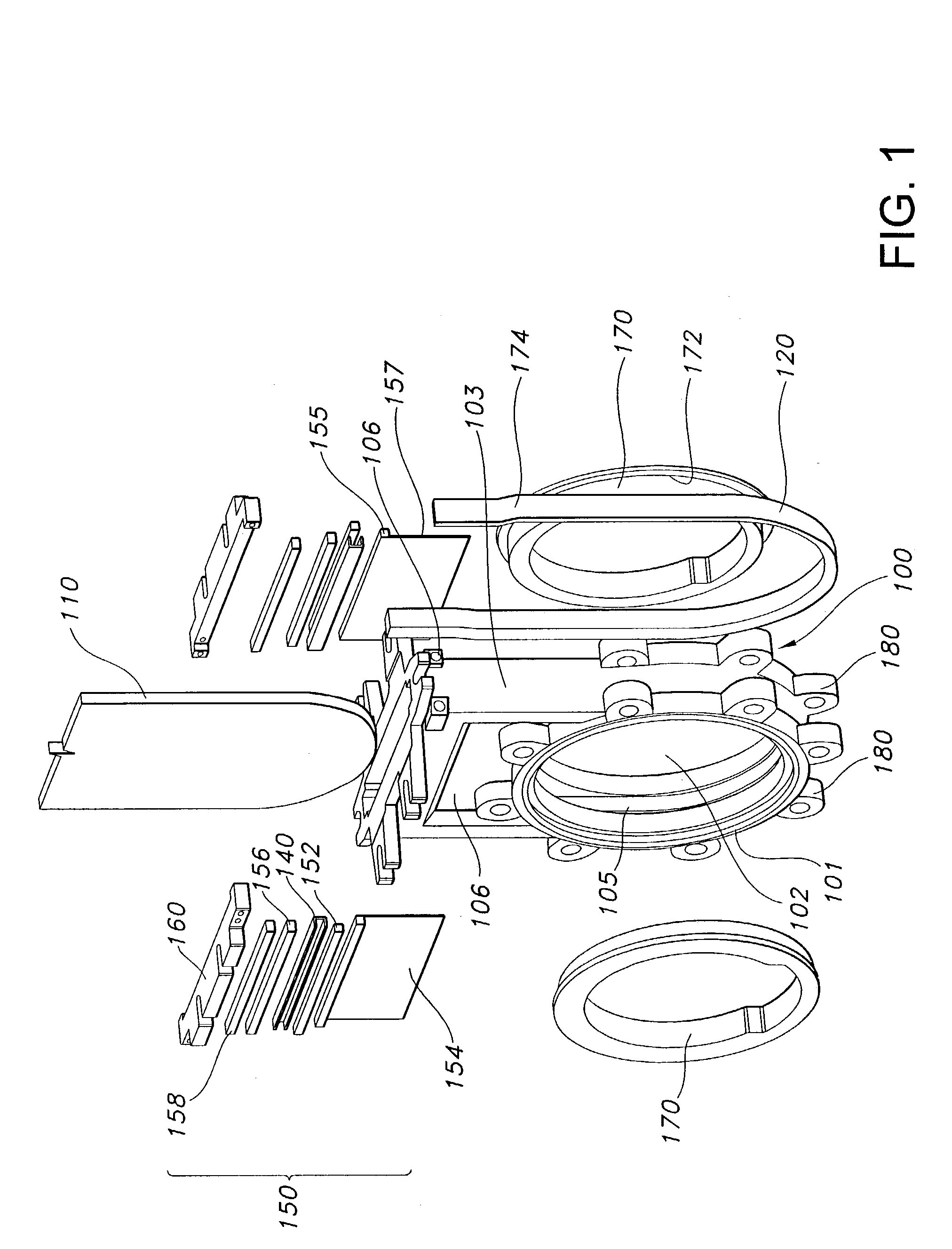
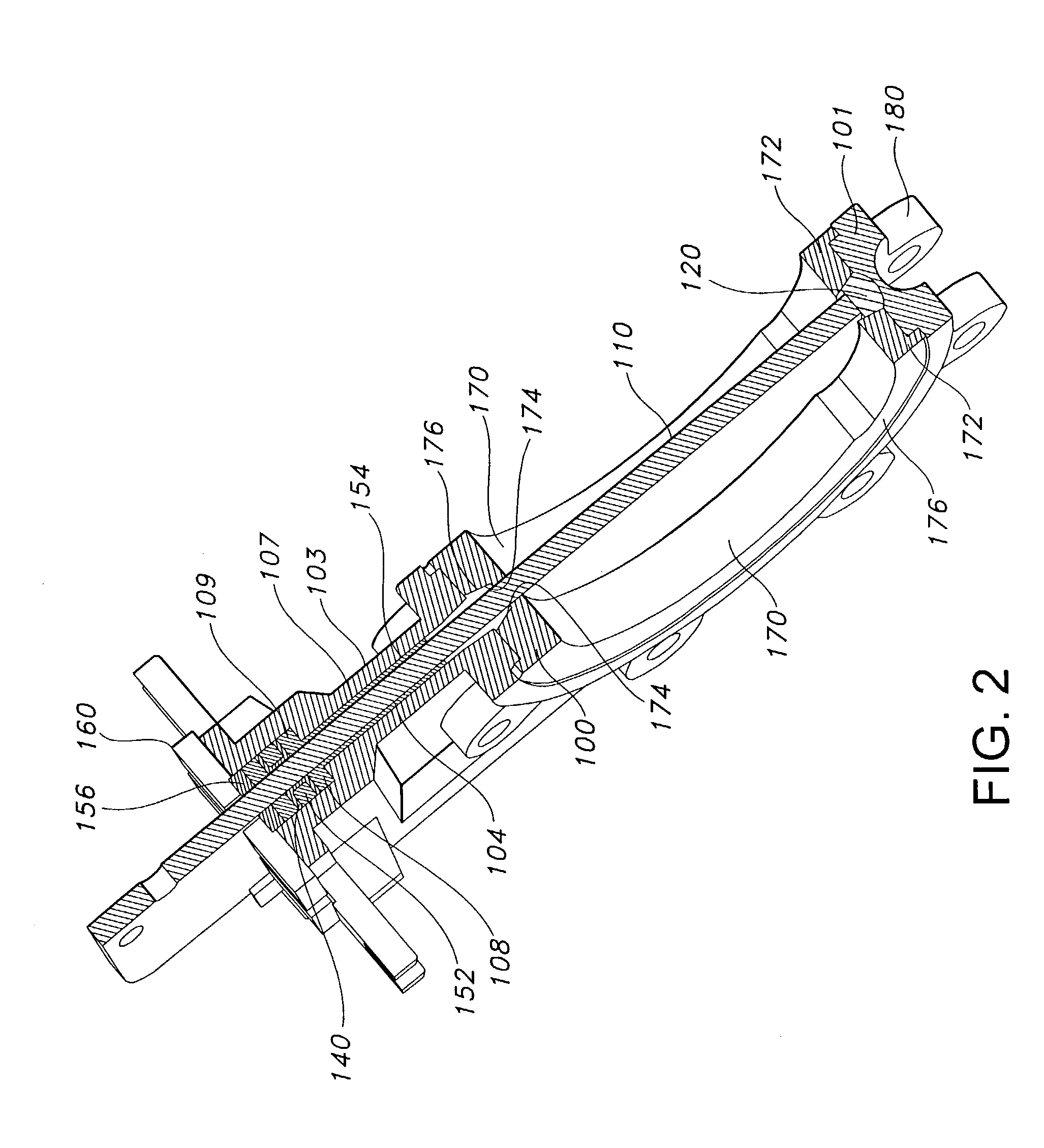
[0013]Referring now to the drawing, FIGS. 1 and 2 show a knife gate valve having a unitary valve body 100, a knife gate 110, a stuffing box seal 150 and a knife gate seat 120.

[0014]The valve body 100 is a unitary piece having a generally cylindrical portion 101 and a generally rectangular (in plain view) box portion 103 extending from the outer periphery of the cylindrical portion. The cylindrical portion 101 includes a flow channel 102 in the form of an opening extending axially from one outer surface to the other. The circular inner wall of the cylindrical portion 101 that bounds the flow channel 102 is formed with a groove 105 that accommodates the knife gate seat 120 for sealing the knife gate 110 in its closed position, i.e., when the knife gate sits in the cylindrical portion and blocks the flow channel.

[0015]The valve body 100 has integral flanges 180 around its outer periphery at each end of the flow channel 102. Flanges 180 mate with flanges formed on a mating vessel (pipe,...


PUM


Abstract

A knife gate valve is provided, comprising: a unitary valve body having a flow channel extending there through, a guide segment and a stuffing box. A knife gate is located in the guide segment, the stuffing box and the flow channel and is slideable between an open and closed position. Lateral seals are provided in the stuffing box and can be replaced while the valve body is connected in its associated fluid system. These seals include an injectable sealing material contained in the stuffing box. A knife gate seat is provided in the valve body for sealing the knife gate and it can be replaced without completely removing the valve body from its associated fluid system.

Description

FIELD OF THE INVENTION[0001]This invention related to generally to a knife gate valve, and more particularly to a knife gate valve having a unitary body and sealing arrangement that facilitates seal maintenance.BACKGROUND OF THE INVENTION[0002]Knife gate valves are used in a variety of applications for quickly shutting off the flow of fluid or other media in a piping system. Typically, knife gate valves have a pair of body members, each formed with a flow passage, fastened together to form a valve body. The body members are spaced apart to provide a seat that accommodates a knife gate when it (the knife gate) is in its closed position, i.e., is operative to shut off flow. Each body member is also formed with an extension and these extensions are also spaced apart to form a housing that accommodates the knife gate in its open position. A knife gate seat arrangement is provided around the flow passages to sealingly engage the knife gate in its closed position and a stuffing box seal a...

Claims


Application Information

Patent Timeline
IPC IPC(8): F16K3/02F16K41/00F16K41/04
CPCF16K3/0227F16K3/0281F16K41/04
Inventor REEVES, SHAINE G.VANDERBERG, CHRISTOPHER A.
Owner ITT MFG ENTERPRISES LLC
Why Eureka
Try Eureka