Injection nozzle for plastic injection moulding equipment

a technology of injection nozzles and injection moulds, which is applied in the field of injection nozzles, can solve the problems of undesired effects and subsequent transmission of significant heat due to conduction, and achieve the effect of reducing the transmission of heat from the injection nozzle to the mould and reducing the transmission of heat to the mould

Inactive Publication Date: 2005-11-01
INGLASS SRL
View PDF9 Cites 11 Cited by
  • Summary
  • Abstract
  • Description
  • Claims
  • Application Information

AI Technical Summary

Benefits of technology

[0006]The space of mutual separation provides an air gap, due to which there is no direct contact between the internal hollow element and the external hollow element and hence the transmission of heat from the injection nozzle to the mould is considerably reduced.
[0007]In accordance with a preferred form of embodiment of the invention, the internal hollow element is provided with a thread that engages with a corresponding thread on the body of the injector. In addition, the contact part of the external hollow element, which can beneficially be elastically sprung, has advantageously a substantially spherical surface and, between this contact part and the remainder of the external hollow element, a reduced-section annular part, which also contributes to reducing the transmission of heat to mould, can be provided to advantage.

Problems solved by technology

With this device, the external hollow element is in direct contact with the internal hollow element along wide areas of its surface, with the consequent transmission of a significant amount of heat due to conduction.
Heat is thus transmitted from the internal hollow element, through the sealed contact part between the external hollow element and the injection mould to which the injection nozzle is applied, to the mould itself, which constitutes an undesired effect.

Method used


Image

  • Injection nozzle for plastic injection moulding equipment
  • Injection nozzle for plastic injection moulding equipment

Examples


Embodiment Construction

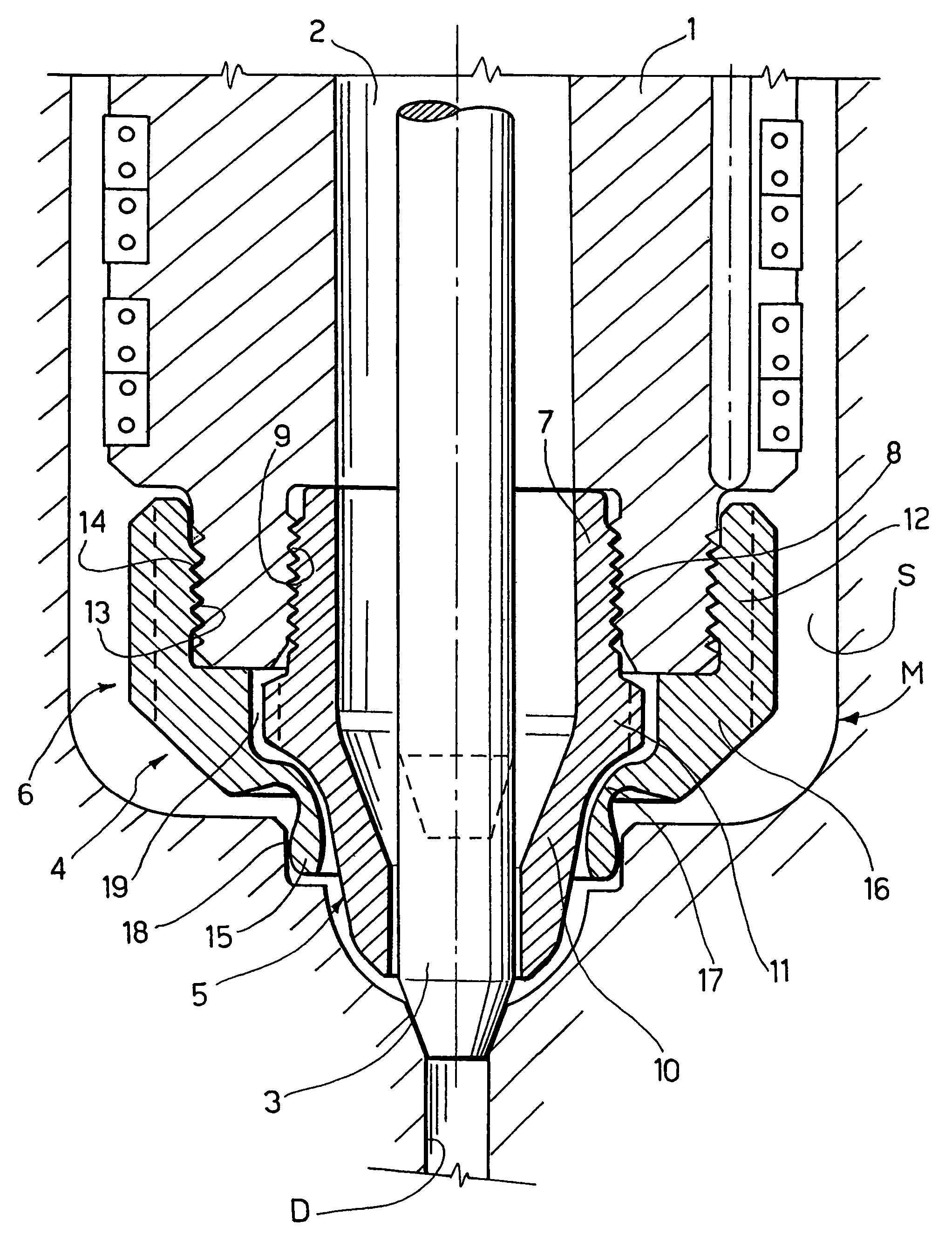
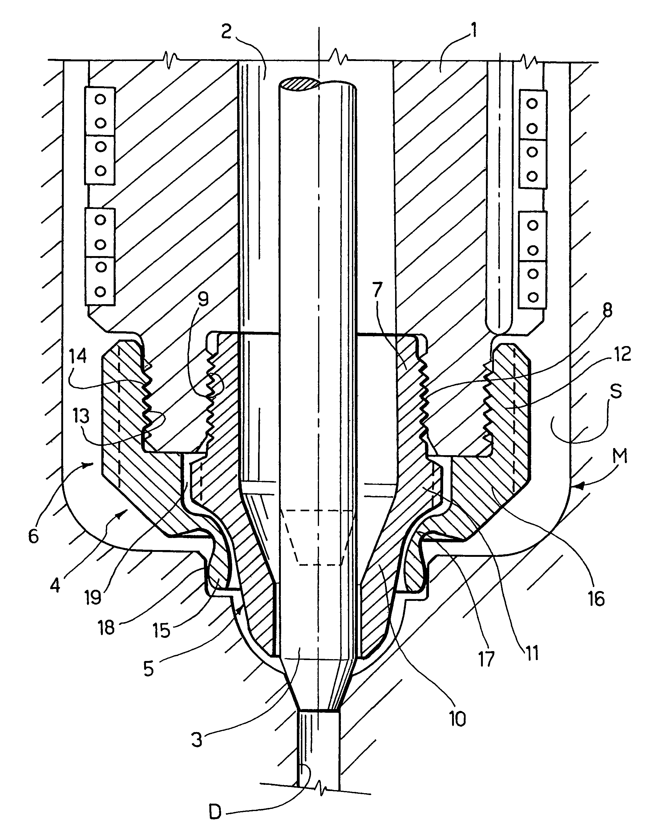
[0009]The injection nozzle represented in the drawing is, taken as a whole, of the generally known type and will therefore not be discussed in detail. For the purposes of the invention, it is sufficient to explain that this injector nozzle, corresponding to that described and illustrated in European patent application No 01830680.3 in the name of A.S. (unpublished at the priority date of this application) for example, is inserted through the space S of a mould M for plastic injection, the cavity of which communicates with the space S through an injection duct D. The injection nozzle presents a body 1 with a central axial passageway 2 for the plastic material to be injected, aligned with the injection duct D and inside which a plug 3 can move axially, cooperating with the injection duct D as a shutter.

[0010]On the part of the injection nozzle 1 facing the injection duct D of the mould M, there is a nozzle tip 4 formed by an internal hollow element 5 made of a material with high therm...


PUM

PropertyMeasurementUnit
thermal conductivityaaaaaaaaaa
thicknessaaaaaaaaaa
temperatureaaaaaaaaaa

Abstract

An injection nozzle for plastic injection moulding equipment having a nozzle tip (4) with an internal hollow element (5) made of a material with high thermal conductivity, and an external hollow element (6) made of a material with a lower thermal conductivity. The internal hollow element (5) is connected to the body (1) of the injector nozzle independently with respect to the external hollow element (6), and a space of mutual separation (19) is defined between the internal and external hollow elements (5, 6).

Description

CROSS-REFERENCE TO RELATED APPLICATIONS[0001]This application is a continuation of U.S. Ser. No. 10 / 323,318, filed Dec. 18, 2002 now U.S. Pat. No. 6,832,909, which claims priority from Italian Patent Application No. TO2001A 001214, filed on Dec. 21, 2001, the entire disclosures of which are incorporated herein by reference.FIELD OF THE INVENTION[0002]The present invention relates to plastic injection moulding equipment in general and, more in particular, an injection nozzle for such equipment, of the type comprising a body with a central passageway and a nozzle tip including an internal hollow element made of a material with high thermal conductivity and an external hollow element made of a material with a lower thermal conductivity.STATE OF THE PRIOR ART[0003]An injection nozzle of this type is described and illustrated, for example, in European Patent EP-B-0633118 in the name of GELLERT, according to which the external hollow element presents a thread at one end that can engage wi...

Claims


Application Information

Patent Timeline
Patent Type & Authority Patents(United States)
IPC IPC(8): B29C45/27
CPCB29C45/278B29C2045/2761B29C2045/2766
Inventor BAZZO, MAURIZIOTREVISIOL, NICO
Owner INGLASS SRL
Why Eureka
Try Eureka