Method for controlling sample introduction in microcolumn separation techniques and sampling device

a sampling device and microcolumn separation technology, applied in the direction of fluid pressure measurement, liquid/fluent solid measurement, peptide measurement, etc., can solve the problem of reducing the detection limits considerably, high noise of detected signals, and well-known bias of actual sample composition

Inactive Publication Date: 2005-11-01
ZEPTOSENS
View PDF23 Cites 12 Cited by
  • Summary
  • Abstract
  • Description
  • Claims
  • Application Information

AI Technical Summary

Benefits of technology

[0010]In a further preferred process step, immediately after the injection of the sample plug, the electrolyte buffer is allowed to advance into the supply channel and into the drain channel at the respective supply and drain ports for a time period, which amounts to at least the migration time of a slowest component within the sample plug from the supply port to the detector. Thus, the sample is pushed back into the respective supply and drain channels and substantially prevented from uncontrollably diffusing into the electrolyte buffer which is transported past the supply and drain ports. In addition the method allows for control of the sample composition within the electrolyte buffer.

Problems solved by technology

These unpredictable amounts of sample components reaching the detector are highly undesirable and result in a high noise of the detected signal, thus reducing the limits of detection considerably.
This method, however, leads to a well-known bias of the actual sample composition due to the differences in the electrophoretic mobilities of the sample components.
In addition, the volume of the introduced sample is very often unknown such, that internal standards have to be used for quantitative analyses.

Method used


Image

  • Method for controlling sample introduction in microcolumn separation techniques and sampling device
  • Method for controlling sample introduction in microcolumn separation techniques and sampling device
  • Method for controlling sample introduction in microcolumn separation techniques and sampling device

Examples


Embodiment Construction

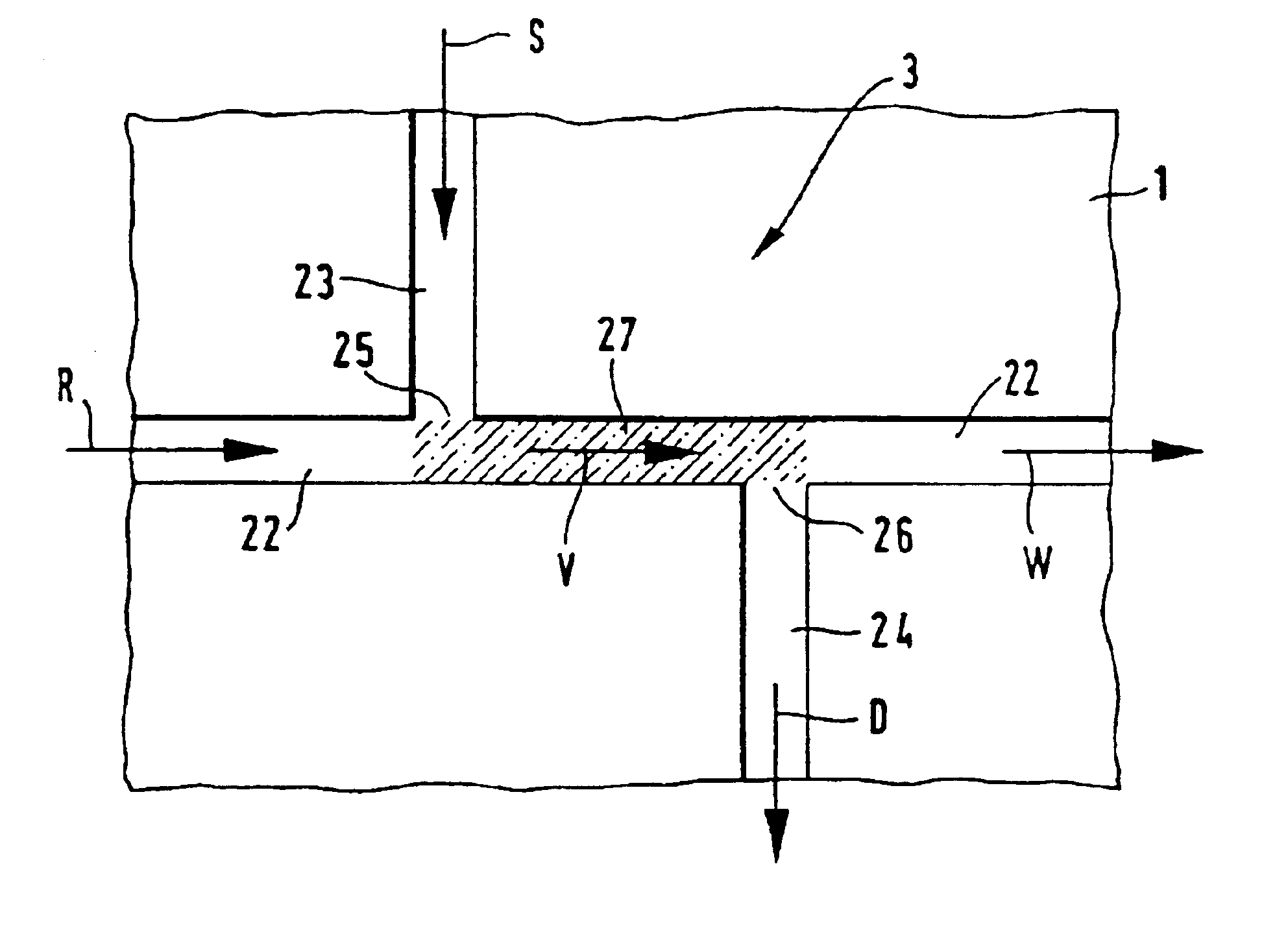
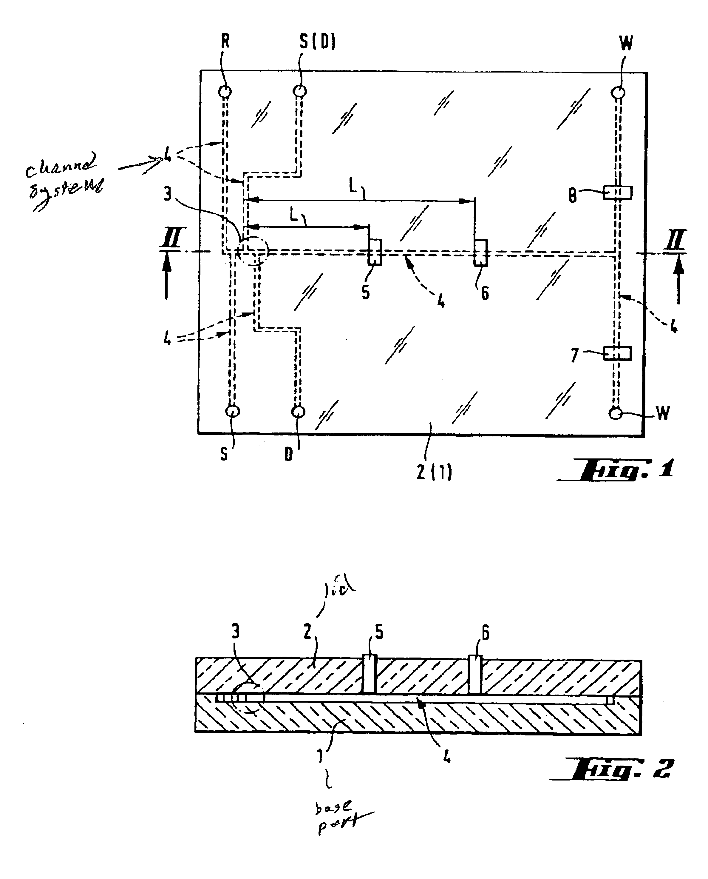
[0017]In FIGS. 1 and 2 an exemplary embodiment of a microcolumn separation device, more particularly of an electrophoretic separation device, is depicted. It comprises a base part 1 and a lid part 2. The base part 1 can be made of glass, monocrystalin silicon or other materials known from semiconductor manufacture, or of a suitable polymer material. The lid part 2 is preferably made of glass. The base part 1 comprises a channel system 4 which is etched, micromachined or otherwise established in its surface. Preferably techniques known from semiconductor manufacture are applied for creating the channel system in the surface of the base part 1. The lid part is provided with through holes R, S, D, W, which communicate with the channel system 4 and are adapted to accommodate and hold the ends of capillary tubes. The lid part 2 is also provided with various ports for light waveguides, which are part of an optical detection system, such as, for example, a fluorescence detection system, or...


PUM

PropertyMeasurementUnit
electric field strengthaaaaaaaaaa
electric fieldaaaaaaaaaa
angleaaaaaaaaaa

Abstract

In a method for controlling sample introduction in microcolumn separation techniques, more particularly in capillary electrophoresis (CE), where a sample is injected as a sample plug into a sampling device which comprises at least a channel for the electrolyte buffer and a supply and drain channel for the sample. The supply and drain channels discharge into the electrolyte channel at respective supply and drain ports. The distance between the supply port and the drain port geometrically defines a sample volume. The injection of the sample plug into the electrolyte channel is accomplished electrokinetically by applying an electric field across the supply and drain channels for a time at least long enough that the sample component having the lowest electrophoretic mobility is contained within the geometrically defined volume. The supply and drain channels each are inclined to the electrolyte channel. Means are provided for electrokinetically injecting the sample into the sample volume. The resistance to flow of the source and drain channels with respect to the electrolyte buffer is at least about 5% lower than the respective resistance to flow of the electrolyte channel.

Description

[0001]This application is a continuation of application Ser. No. 08 / 226,605, filed Apr. 12, 1994, now U.S. Pat. No. 6,280,589, which claims the benefit of priority to German Application Serial No. 93810272.0, filed on Apr. 15, 1993, both of which are incorporated herein by reference.[0002]The present invention concerns a method for controlling sample introduction in microcolumn separation techniques. The invention also concerns a respective sampling device for a controlled sample introduction in microcolumn separation techniques.BACKGROUND OF THE INVENTION[0003]Microcolumn separation techniques, in particular capillary electrophoresis has become a very interesting separation technique which is used as part of a sensor or a chemical analysis system. One major reason for this is the great efficiency of the method as a separation technique. The sampling methods usually applied in capillary electrophoresis are: injection of a sample with a syringe, via a septum, in an injection block, t...

Claims


Application Information

Patent Timeline
Patent Type & Authority Patents(United States)
IPC IPC(8): G01N27/447G01N1/10G01N37/00G01N1/00
CPCC07K1/26G01N27/44743G01N27/44791
Inventor MANZ, ANDREASHARRISON, D. JEDEFFENHAUSER, CARLO S.
Owner ZEPTOSENS
Why Eureka
Try Eureka