End-column fluorescence detection for capillary array electrophoresis

a capillary array and fluorescence detection technology, applied in the direction of fluorescence/phosphorescence, liquid/fluent solid measurement, peptides, etc., can solve the problems of inability to detect the intensity of the array, the number of rows that can be illuminated with sufficient optical intensity is limited, and the intensity incident on each successive row is exponentially decreased

Inactive Publication Date: 2006-08-10
MASSACHUSETTS INST OF TECH
View PDF9 Cites 33 Cited by
  • Summary
  • Abstract
  • Description
  • Claims
  • Application Information

AI Technical Summary

Benefits of technology

[0012] In accordance with another aspect of the invention, an apparatus is provided for optical interrogation, generally, of a plurality of substantially coplanar loci. The apparatus has an imaging optical arrangement having one or more focal regions, the imaging optical arrangement disposed at a displacement with respect to the substantially coplanar loci so as to place each locus within a focal region of the imaging optical arrangement. The apparatus also has a source for illuminating each of the plurality of substantially coplanar loci via the optical arrangement and an optical detector for detecting light imaging each of the plurality of substantially coplanar loci after said light has been collected by the imaging optical arrangement. The optical arrangement may include an array of imaging optical elements, each of which is characterized by an area, a numerical aperture, and a focal region.
[0013] In accordance with various alternate embodiments of the invention, the optical elements are reflecting elements, such as parabolic reflectors, or they may be lenslets. The area and numerical aperture of each optical element may be chosen so as to provide an increase in optical collection solid angle for each of the substantially coplanar loci, and the numerical aperture of each optical element, in particular, may exceed 0.3. The source of illumination may include an LED array, and may generally include an array of incoherent light sources and an optical diffuser. The optical detector may be a CCD array, and, more particularly, an impact-ionizing CCD array.
[0014] In accordance with yet a further aspect of the present invention, a method is provided for manufacturing an array of lenslets. The method has the steps of fashioning a plurality of détentes in a mold and injecting acrylic into the mold. The step of fashioning the détentes may include one or more of the steps of milling with a ball-end milling tool, investment casting, single point diamond turning, or grinding.

Problems solved by technology

Each of the prior art systems, however, suffers from notable limitations on scalability—regrettable in view of clearly advantageous research avenues that would be opened were truly high sample volume throughputs enabled.
Where two-dimensional arrays of capillaries have been proposed, a similar limitation exists, in that light that illuminates a second row has already traversed a first row.
Thus, the illumination intensity incident on each successive row decreases exponentially, in general, such that the number of rows that can be illuminated with sufficient optical intensity is limited.
Moreover, homogeneity of the illuminating field is further impaired by the variation in refractive index of the successive media through which the beam passes.
Such systems, as commercialized by Applied Biosystems, of Foster City, Calif., are limited by the distance over which the excitation laser beam remains collimated.
In addition to the limitations on scalability imposed, in the prior art, by the requisite size of detectors, collection optics, or optical power constraints of excitation lasers, a further, and considerable, limitation is the failure to provide for or permit collection, or sequestration, of molecules effluent from respective electrophoresis channels.
Post-processing analysis is valuable in many applications and is unavailable where fluorescence detection occurs outside the capillaries in a common pooled buffer medium and is impractical when detection occurs at a distance away from the distal end of the capillaries.

Method used


Image

  • End-column fluorescence detection for capillary array electrophoresis
  • End-column fluorescence detection for capillary array electrophoresis
  • End-column fluorescence detection for capillary array electrophoresis

Examples


Embodiment Construction

[0039] Various techniques of optical identification or analysis of materials entail the excitation of a sample with light of one wavelength (or band of wavelengths) and detection of subsequent emission at the same or other wavelengths. Such techniques include scattering modalities such as Raman spectroscopy, as well as fluorescence, where a target molecule is labeled with a fluorophore (such as the Alexa 488 dye that is used herein for descriptive purposes and without limitation) that emits light at a characteristic emission wavelength when the fluorophore is excited by exciting radiation of equal or greater energy to the emitted fluorescence.

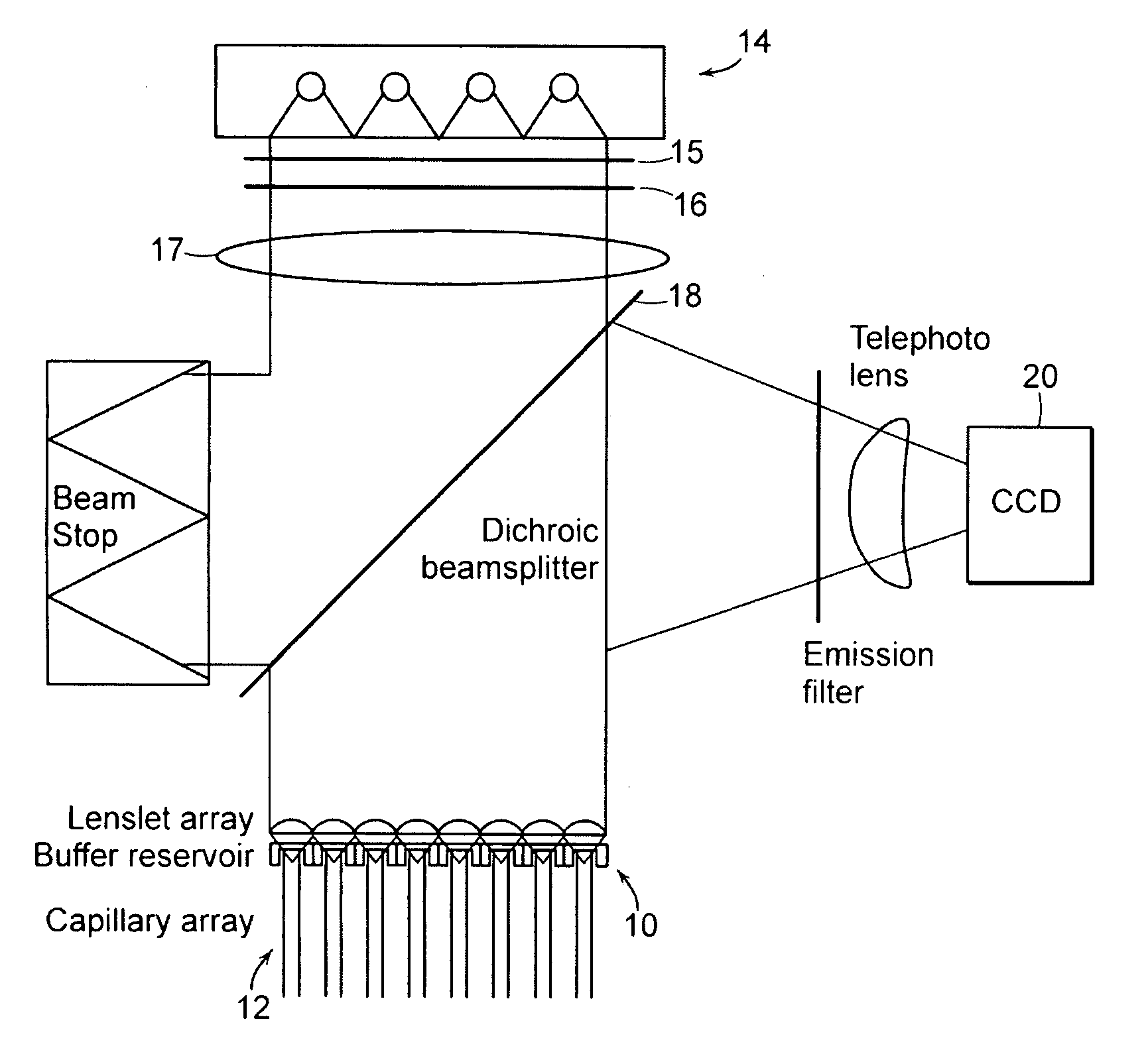
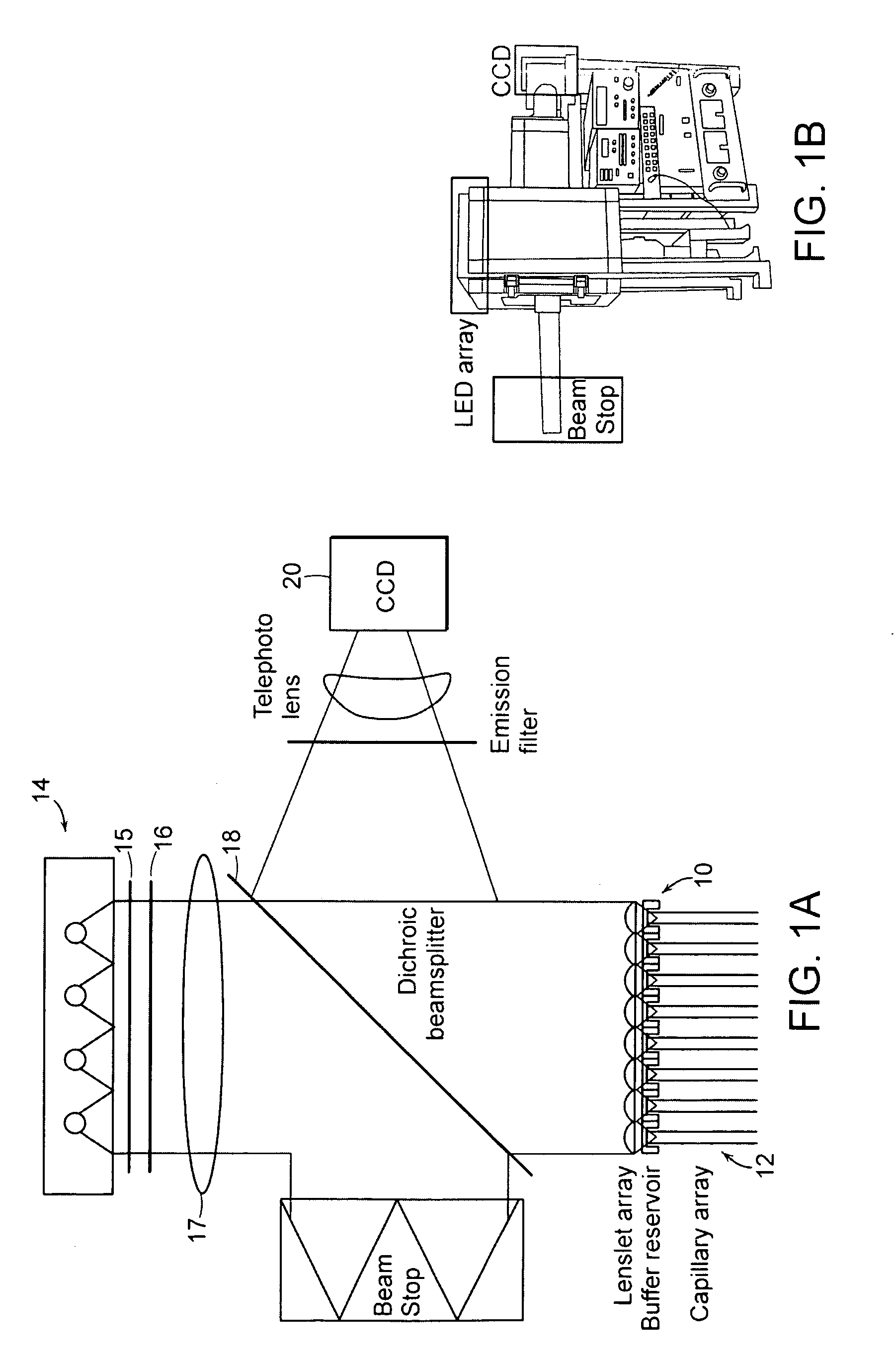
[0040] Some basic elements that may be employed in the practice of the present invention are now introduced with reference to FIG. 1A, where an apparatus for optically interrogating a plurality of loci is shown. The loci to be interrogated lie substantially within a focal plane 10 that encompasses, for example, the ends of an array of substant...


PUM

PropertyMeasurementUnit
wavelengthaaaaaaaaaa
diameteraaaaaaaaaa
diameteraaaaaaaaaa

Abstract

A massively parallel electrophoresis system comprised of capillaries, with means for parallel imaging of the capillary ends. The capillaries are aligned with parallel longitudinal axes and a set of ends that are substantially coplanar. The electrophoresis system has a source of excitation radiation for illuminating the ends while an imaging optical arrangement places substantially coplanar loci, one per capillary, within a focal region of the imaging optical arrangement. A detector module receives electromagnetic radiation that is emitted by fluorophores within the capillaries upon excitation by the excitation radiation and transmitted to the detector module by way of the imaging optical arrangement. A manifold may terminate the array of electrophoresis capillaries, wherein the manifold has a platen with a plurality of recessions for receiving each of a the ends of the array of capillaries, and a septum disposed adjacent to the platen for penetration by the ends of the array of capillaries when inserted into the platen. Electrophoresis products may be separated by segregating effluent from one or more capillaries of the array.

Description

[0001] The present application claims priority from U.S. Provisional Patent Application Ser. No. 60 / 651,681, filed Feb. 10, 2005, which application is incorporated herein by reference.TECHNICAL FIELD [0002] The present invention relates to a device and method for parallel optical detection of fluorescence from the ends of multi-capillary arrays performing electrophoretic separations. BACKGROUND OF THE INVENTION [0003] Inroads have been made toward increasing the throughput of electrophoresis systems for separating and identifying DNA molecules and other macromolecules, as typically practiced for sequencing and genotyping operations. Typical systems employ the migration of samples, in applied electric fields, through some number of parallel capillaries or channels, and detection of fluorescence or ultra-violet (UV) absorption in molecules selectively excited by optical illumination. Each of the prior art systems, however, suffers from notable limitations on scalability—regrettable in...

Claims


Application Information

Patent Timeline
Patent Type & Authority Applications(United States)
IPC IPC(8): G01N21/00G01N21/64
CPCG01N21/6452G01N21/6456G01N27/44721
Inventor FOREST, CRAIG R.HUNTER, IANBALL, NATHAN B.THILLY, WILLIAM G.
Owner MASSACHUSETTS INST OF TECH
Why Eureka
Try Eureka