Apparatus for monitoring a sliding contact element in an electrical rotating machine

Active Publication Date: 2005-11-01
SIEMENS AG
View PDF16 Cites 44 Cited by
  • Summary
  • Abstract
  • Description
  • Claims
  • Application Information

AI Technical Summary

Benefits of technology

[0011]An embodiment of the invention may be based on an object of specifying an apparatus for monitoring a sliding contact elem

Problems solved by technology

When the carbon brushes are replaced, these lines must first of all be detached and must th

Method used


Image

  • Apparatus for monitoring a sliding contact element in an electrical rotating machine
  • Apparatus for monitoring a sliding contact element in an electrical rotating machine
  • Apparatus for monitoring a sliding contact element in an electrical rotating machine

Examples


Embodiment Construction

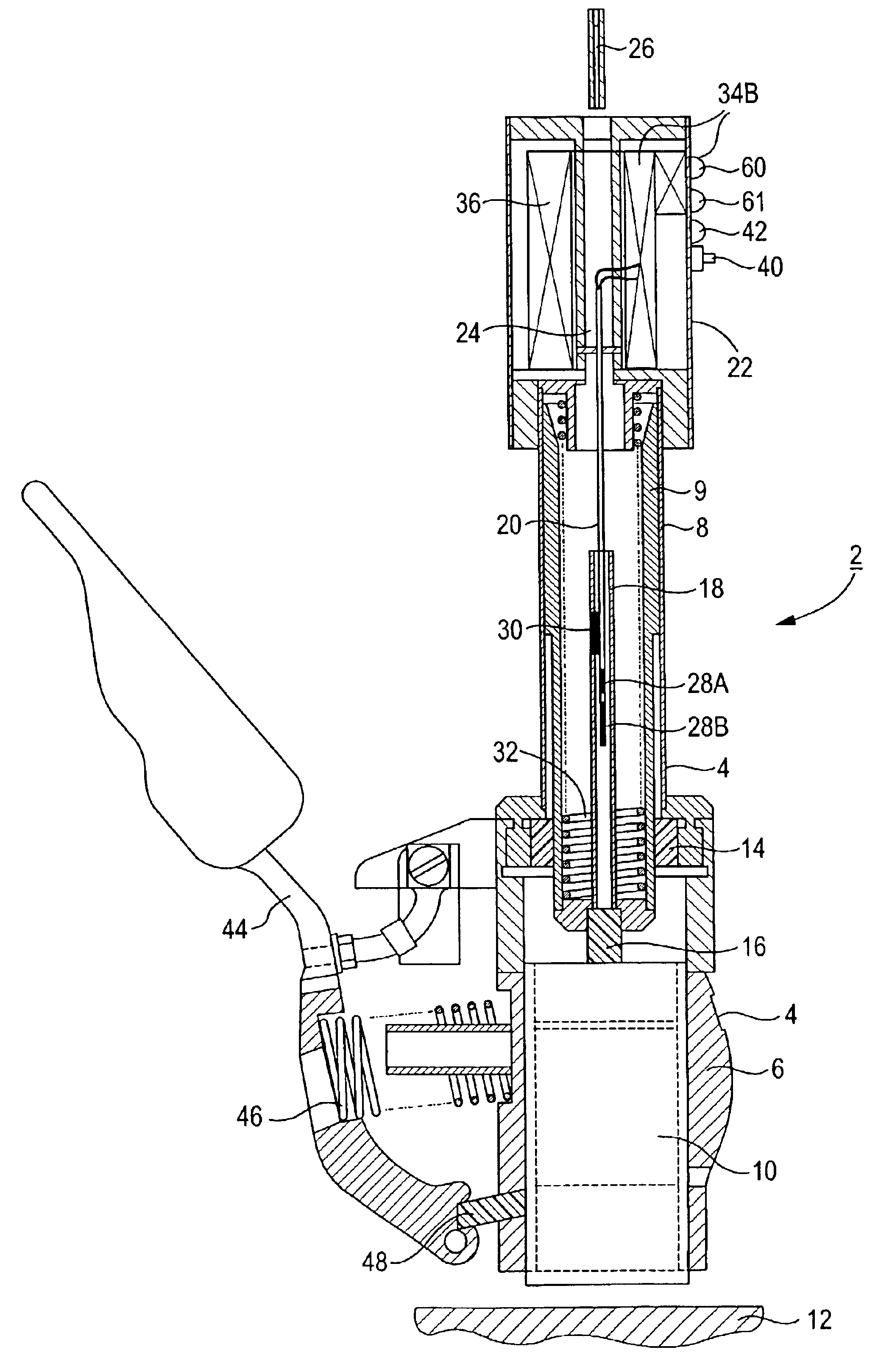
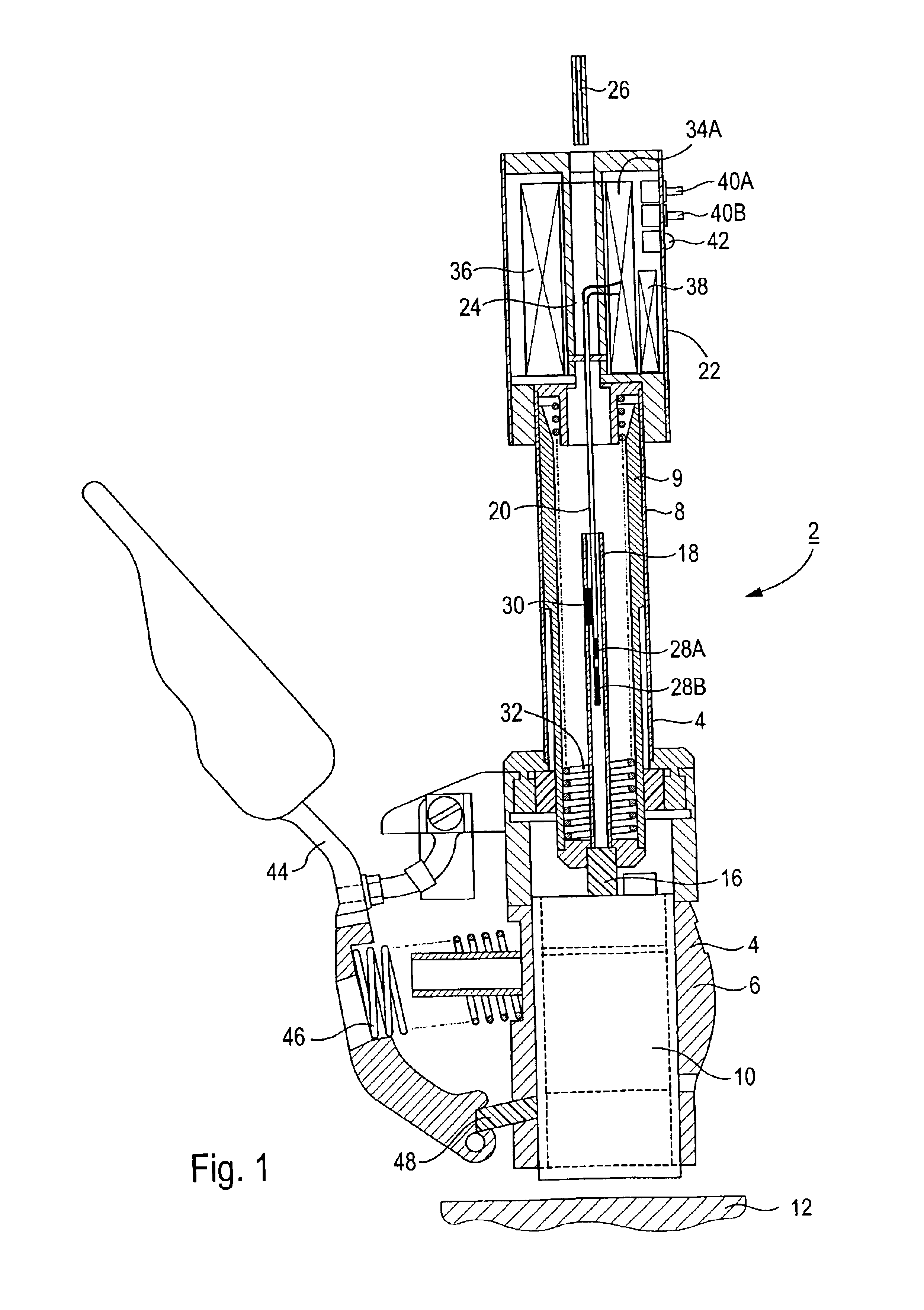
[0043]A plug-in brush holder 2 as shown in FIG. 1 has a housing 4 which, in a lower region, has a sliding contact receptacle 6, and a tubular housing part 8 connected to it. A telescopic tube 9 is arranged in the interior of the housing part 8. A sliding contact element 10, in particular a carbon brush, is arranged in the sliding contact receptacle 6. During operation, the sliding contact element 10 is in contact with a slip-ring 12.

[0044]The telescopic tube 9 is passed through an end-face boundary 14 of the sliding contact receptacle 6, to the latter. The end faces of the telescopic tube 9 are sealed, and the connecting element 16 on the telescopic tube 9 presses against the head face of the sliding contact element 10. A plastic tube 18, which extends into the interior of the telescopic tube 9, is seated on this connecting element 16. An instrumentation lance 20 in turn extends into the plastic tube 18, from above. This instrumentation lance 20 is likewise tubular, and is connected...


PUM


Abstract

An apparatus for monitoring a sliding contact element in an electrical rotating machine, in particular a generator, includes a holder for the sliding contact element and a sensor for detection of a state variable of the sliding contact element. An evaluation unit is also provided for evaluation of the state variable which is detected by the sensor, with signals from the sensor being transmitted to the evaluation unit without using wires. The wire-free transmission makes the apparatus particularly maintenance-friendly.

Description

[0001]The present application hereby claims priority under 35 U.S.C. Section 119 on European Patent application number 01115808.6 filed Jun. 28, 2001, the entire contents of which are hereby incorporated by reference.FIELD OF THE INVENTION[0002]The invention generally relates to an apparatus for monitoring a sliding contact element in a electrical rotating machine. In particular, it preferably relates to a turbo-generator, having a holder for the sliding contact element and having a sensor for detection of a state variable of the sliding contact element, and having an evaluation unit for evaluation of the state variable which is detected by the sensor.[0003]The invention may preferably relate, in particular, to a plug-in brush holder for a turbo-generator with slip-rings, or for an exciter machine with commutators. A carbon brush is inserted into the plug-in brush holder, as a replaceable sliding contact element.[0004]An electrical rotating machine generally has a field winding on a...

Claims


Application Information

Patent Timeline
IPC IPC(8): H01R39/00H01R39/58G08C17/00G01B7/00G08C23/00H02K11/25H02K11/35
CPCH01R39/58H02K11/25H02K11/35H02K5/14
Inventor KLAAR, JUERGEN
Owner SIEMENS AG
Why Eureka
Try Eureka