Method and apparatus for scheduling of requests to dynamic random access memory device

Inactive Publication Date: 2005-11-01
META PLATFORMS TECH LLC
View PDF21 Cites 54 Cited by
  • Summary
  • Abstract
  • Description
  • Claims
  • Application Information

AI Technical Summary

Benefits of technology

[0005]The present invention provides for the scheduling of requests to one resource, such as a DRAM subsystem, from a plurality of initiators. E

Problems solved by technology

Yet re-ordering of requests for thread QOS or DRAM efficiency reasons can compromise a strongly ordered memory model.
In this case, DRAM scheduling for efficiency is more constrained than it needs to be resulting in lower DRAM efficiency.
This kind of system has

Method used


Image

  • Method and apparatus for scheduling of requests to dynamic random access memory device
  • Method and apparatus for scheduling of requests to dynamic random access memory device
  • Method and apparatus for scheduling of requests to dynamic random access memory device

Examples


Embodiment Construction

[0014]The mechanism described herein applies to systems where multiple independent initiators share a dynamic random access memory (DRAM) subsystem.

[0015]In one embodiment, the present invention allows different initiators to be given a pre-defined quality of service independent of one another while at the same time keeping DRAM efficiency as high as possible and presenting a strong memory ordering model to the initiators.

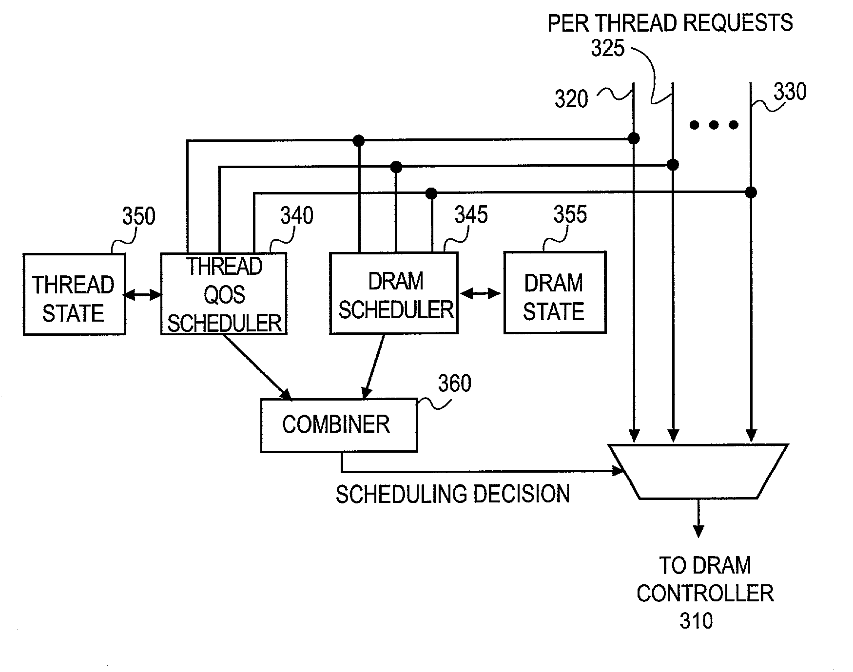
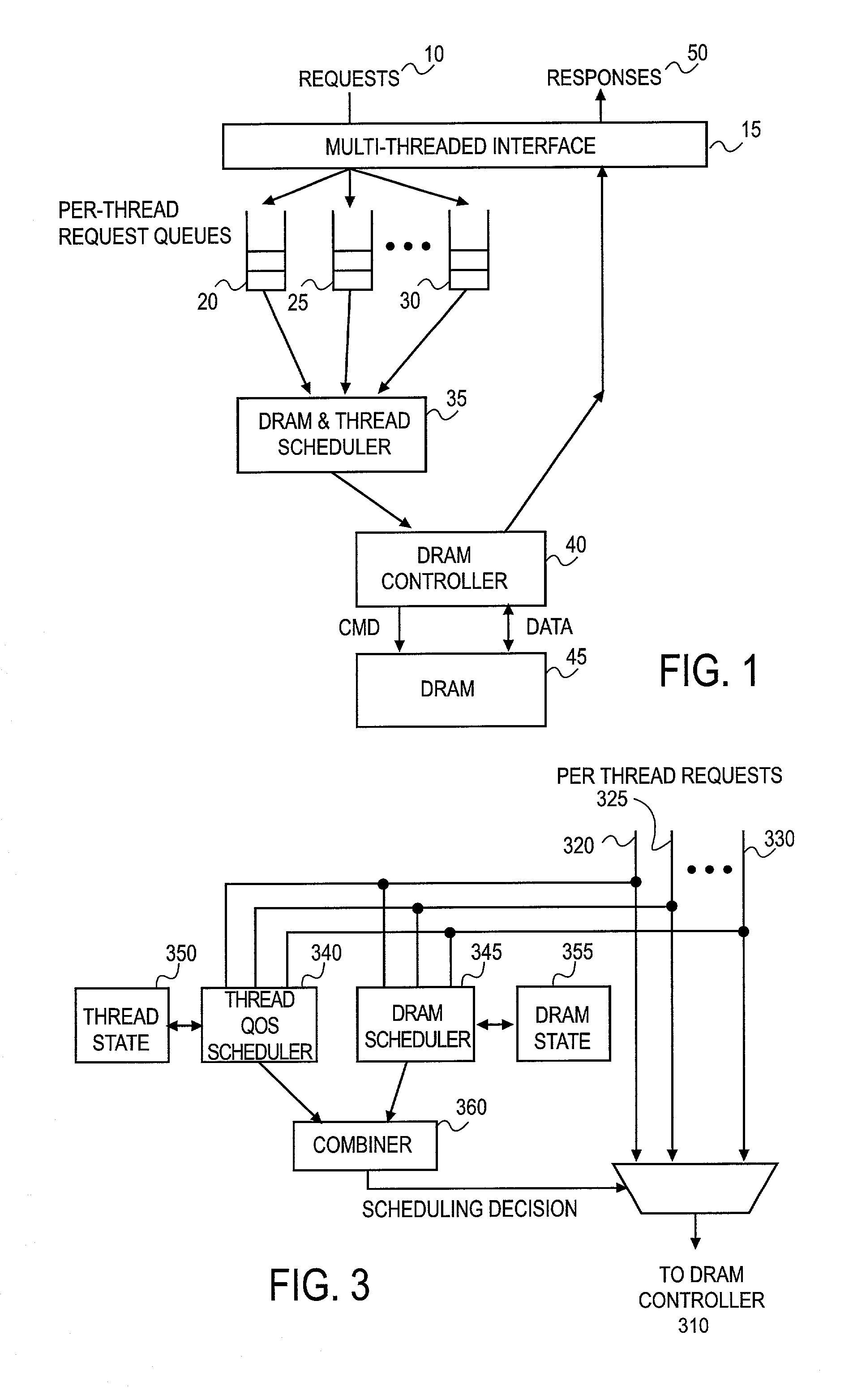
[0016]FIG. 1 shows a high-level block diagram of one embodiment of a DRAM scheduling system. Requests 10 from different initiators arrive over a multi-threaded interface 15. An initiator may be embodied as a device or a process. Requests 10 from different initiators are communicated across different threads that are identified by different thread identifiers (“thread IDs”) at the interface. This allows requests to be split by thread (or initiator) into per-thread request queues, e.g. 20, 25, 30. Requests from these thread queues 20, 25, 30 are presented in parallel...


PUM


Abstract

The present invention provides for the scheduling of requests to one resource from a plurality of initiator devices. In one embodiment, scheduling of requests within threads and scheduling of initiator device access is performed wherein requests are only reordered between threads.

Description

FIELD OF THE INVENTION[0001]The mechanism described herein applies to systems where multiple independent initiators are sharing a dynamic random access memory (DRAM) subsystem.BACKGROUND[0002]In systems that are built on a single chip it is not uncommon that there are several independent initiators (such as microprocessors, signal processors, etc.) accessing a dynamic random access memory (DRAM) subsystem that for cost, board area, and power reasons is shared among these initiators. The system may require different qualities of service (QOS) to be delivered for each of the initiators. Secondly, the memory ordering model presented to the initiators is important. Ideally, the initiators want to use a memory model that is as strongly ordered as possible. At the same time, the order in which DRAM requests are presented to the DRAM subsystem can have a dramatic effect on DRAM performance. Yet re-ordering of requests for thread QOS or DRAM efficiency reasons can compromise a strongly orde...

Claims


Application Information

Patent Timeline
IPC IPC(8): G06F13/16G06F12/00G06F12/02
CPCG06F13/1621
Inventor WEBER, WOLF-DIETRICH
Owner META PLATFORMS TECH LLC
Why Eureka
Try Eureka