Strapping machine with automatic chute opening system

a technology of automatic chute opening and strapping machine, which is applied in the field of strapping machine with automatic chute opening system, can solve the problems of time-consuming, subject to additional stress, and known machines have no “easy” way to make such height adjustments, and achieve the effect of low friction

Active Publication Date: 2005-11-08
SIGNODE IND GRP
View PDF4 Cites 24 Cited by
  • Summary
  • Abstract
  • Description
  • Claims
  • Application Information

AI Technical Summary

Benefits of technology

[0015]A strapping machine configured to feed a strapping material around a load, position, tension and seal the strapping material around the load, includes an improved chute opening system that automatically opens the strap chute upon opening or pivoting of a machine work surface.
[0020]A preferred arrangement includes a roller at an end of the arm for engaging the lower surface of the work surface. The roller provides a smooth (low friction) interface between the arm and the work surface. In a present embodiment, the contact arm is configured such that when the works surface is pivoted downwardly to an operating position, the contact arm (at the roller) contacts the work surface at a location beyond a pivot of the work surface. This results in eliminating the upward force on the work surface (which would urge the surface up or open) when the surface is fully down and in the operating mode.

Problems solved by technology

This can be quite time consuming particularly if, as often happens, the weld blade requires frequent cleaning.
In addition, in that the conveyor is a load-bearing surface, it may be subjected to additional stresses beyond those to which the machine, generally is subjected.
Known machines have no “easy” way to make such height adjustments.

Method used


Image

  • Strapping machine with automatic chute opening system
  • Strapping machine with automatic chute opening system
  • Strapping machine with automatic chute opening system

Examples


Embodiment Construction

[0062]While the present invention is susceptible of embodiment in various forms, there is shown in the drawings and will hereinafter be described a presently preferred embodiment with the understanding that the present disclosure is to be considered an exemplification of the invention and is not intended to limit the invention to the specific embodiment illustrated.

[0063]It should be further understood that the title of this section of this specification, namely, “Detailed Description Of The Invention”, relates to a requirement of the United States Patent Office, and does not imply, nor should be inferred to limit the subject matter disclosed herein.

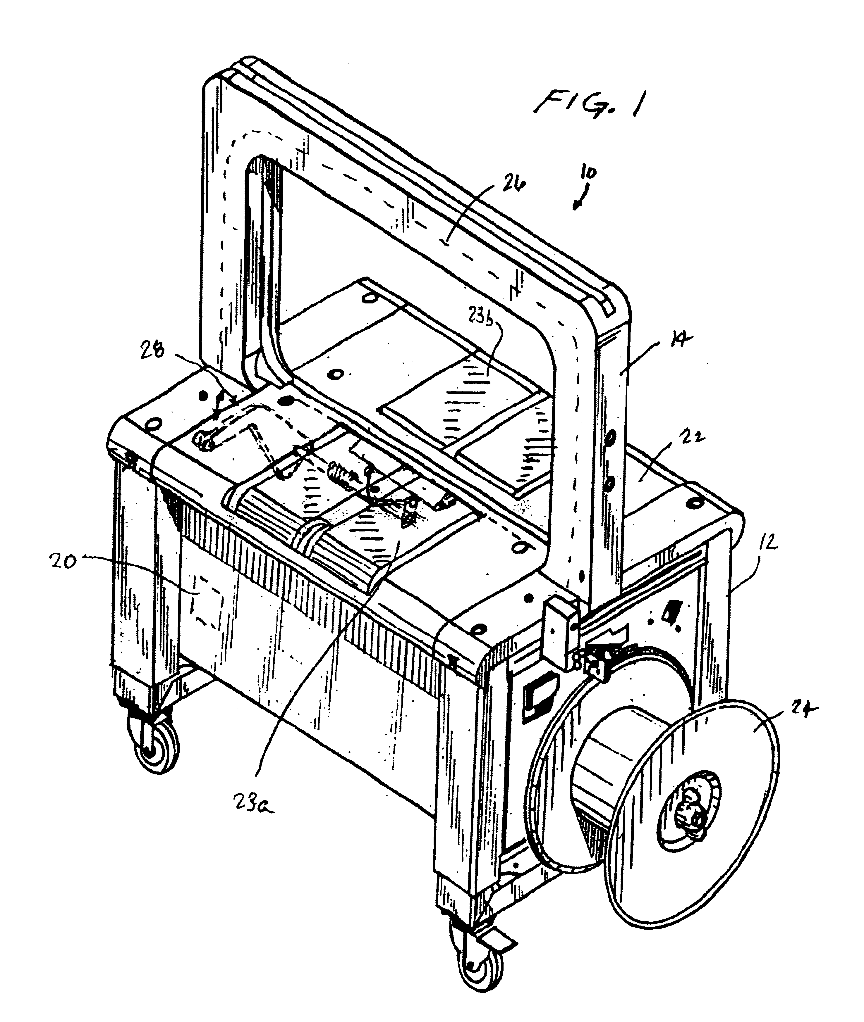
[0064]Referring to the figures and in particular FIG. 1, there is shown a strapping machine 10 embodying the principles of the present invention. The strapping machine 10 includes, generally, a frame 12, a strap chute 14, a feed assembly 16 and a weld head 18. A controller 20 provides automatic operation and control of the strapper 10. A...


PUM


Abstract

A strapping machine configured to feed a strapping material around a load, position, tension and seal the strapping material around the load, includes a chute opening system to open a lower portion of the strap chute upon upwardly pivoting a portion of the work surface. Such a machine includes a machine frame, a work surface for supporting the load in the strapping machine, at least a portion of which is upwardly pivotal. A strap chute carries the strapping material around the load and releases the strapping material from the strap chute. The strap chute defines a strap path along the chute. The chute is movable between an operating position in which the strapping material is conveyed along the chute and a release position in which the strap chute is moved longitudinally to release the strapping material from the chute for positioning around the load. A weld head seals the strapping material onto itself. At least a portion of the weld head is disposed along the strap path below the work surface. The chute opening system is operably connected to the chute and is engageable with the upwardly pivotal portion of the work surface. The chute opening system includes a contact arm for engaging a lower surface of the work surface. The contact arm is operably connected to the chute such that upward pivoting of the work surface moves the chute from the operating position to the release position.

Description

CROSS REFERENCE TO RELATED APPLICATION DATA[0001]This application claims the benefit of priority of U.S. Provisional Patent Application Ser. No. 60 / 479,231, filed Jun. 17, 2003.BACKGROUND OF THE INVENTION[0002]The present invention is directed to an improved strapping machine. More particularly, the present invention is directed to a strapping machine having a system for automatically opening the chute with the opening of the table top or work surface.[0003]Strapping machines are in widespread use for securing straps around loads. One type of known strapper includes a strapping head and drive mechanism mounted within a frame. A chute is mounted to the frame, through which the strapping material is fed.[0004]In a typical stationary strapper, the chute is mounted at about a work surface, and the strapping head is mounted to a horizontal portion of the chute, below the work surface. The drive mechanism is also mounted below the work surface, near to the strapping head. The drive mechan...

Claims


Application Information

Patent Timeline
Patent Type & Authority Patents(United States)
IPC IPC(8): B65B13/06B65B13/00B65B13/18
CPCB65B13/06B65B13/18
Inventor BOBREN, ALLAN J.LININGER, JOSEPH E.
Owner SIGNODE IND GRP
Why Eureka
Try Eureka