Microwave ablation instrument with insertion probe

a microwave ablation and probe technology, applied in the field of microwave ablation instruments, can solve the problems of unacceptably increasing surgical risk, early postoperative intrahepatic recurrence, poor prognosis of patients with unresectable hepatocellular carcinoma (hcc) tumors,

Inactive Publication Date: 2005-11-08
MAQUET CARDIOVASCULAR LLC
View PDF32 Cites 111 Cited by
  • Summary
  • Abstract
  • Description
  • Claims
  • Application Information

AI Technical Summary

Benefits of technology

[0014]Preferably, the antenna device is integrally formed by removing a portion of the outer conductor to expose a portion of the dielectric material medium. Thus, the transverse cross-sectional dimension of the antenna device is substantially equal or smaller than that of the transmission line. In one embodiment, the transverse cross-sectional dimension of dielec

Problems solved by technology

This is due to the severity of the associated liver cirrhosis (which may unacceptably increase the surgical risk) and to the frequent multifocality of the tumor.
The latter is a critical issue since small doughter nodules may accompany the main tumor and go undetected causing early postoperative intrahepatic recurrences.
The prognosis for patients with unresectable hepatocellular carcinoma (HCC) tumors is extremely poor, however.
The greatest drawback of PEI is represented by the difficulty to treat tumors larger than 3 cm.
In these cases, alcohol diffusion is incomplete, being impeded by the texture of the tumor.

Method used


Image

  • Microwave ablation instrument with insertion probe
  • Microwave ablation instrument with insertion probe
  • Microwave ablation instrument with insertion probe

Examples


Embodiment Construction

[0032]While the present invention will be described with reference to a few specific embodiments, the description is illustrative of the invention and is not to be construed as limiting the invention. Various modifications to the present invention can be made to the preferred embodiments by those skilled in the art without departing from the true spirit and scope of the invention as defined by the appended claims. It will be noted here that for a better understanding, like components are designated by like reference numerals throughout the various FIGURES.

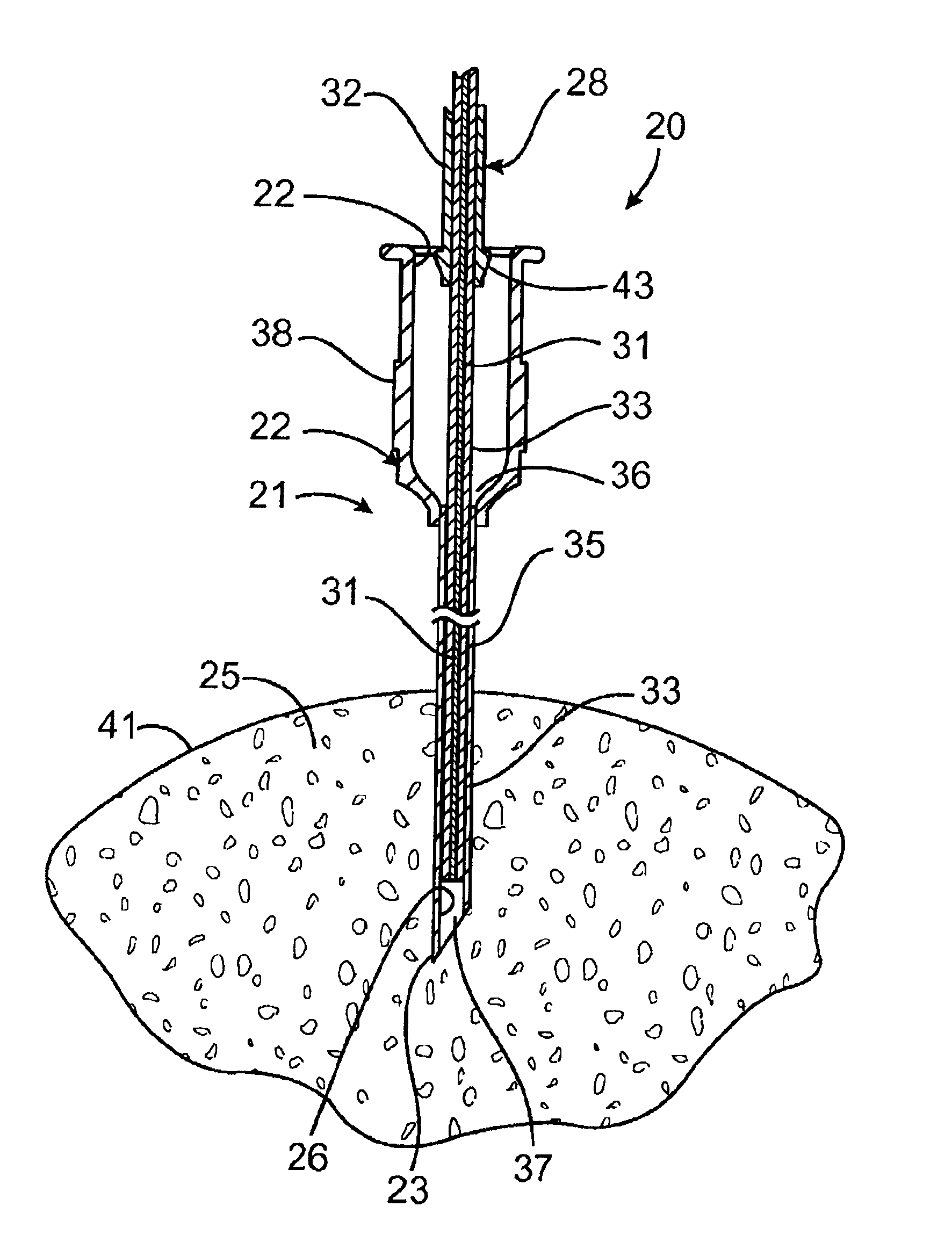
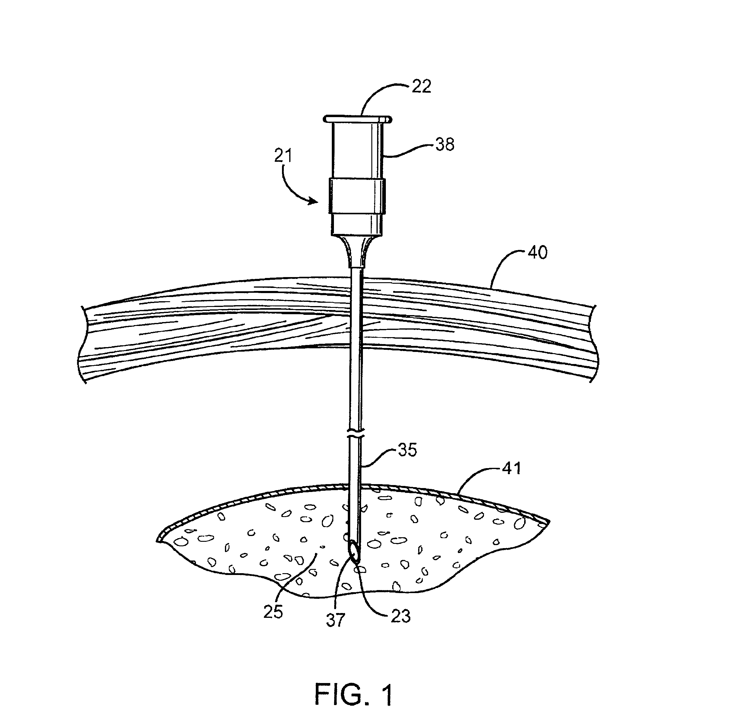
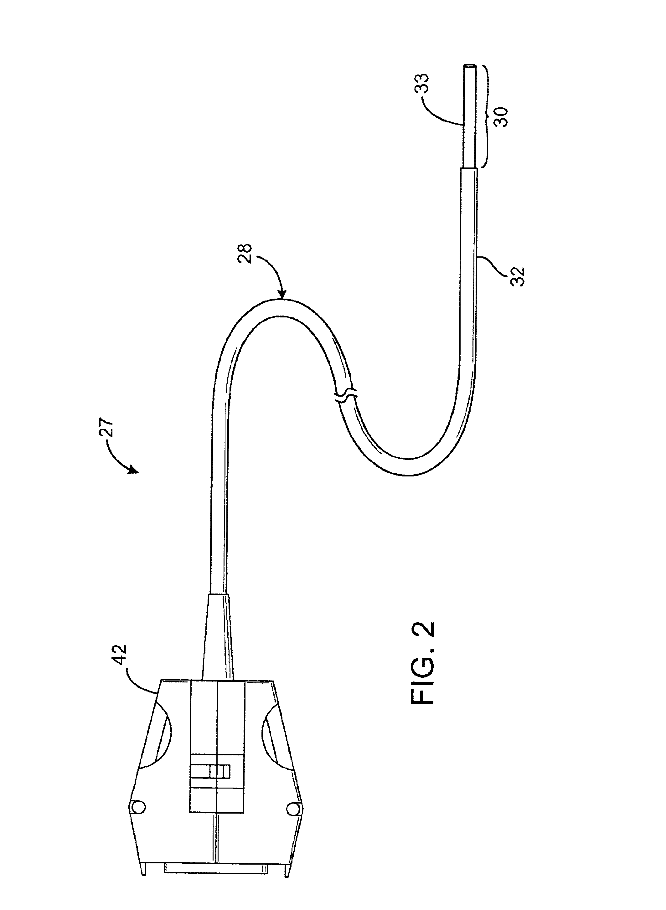
[0033]Turning now to FIGS. 1-3, a microwave ablation assembly, generally designated 20, is provided including a relatively thin, elongated probe 21 having a proximal access end 22 and an opposite distal penetration end 23 adapted to penetrate into bio-tissue 25. The probe 21 further defines an insert passage 26 extending therethrough from the access end 22 to the penetration end 23 thereof. The ablation assembly 20 further includes...


PUM


Abstract

A microwave ablation assembly and method including a relatively thin, elongated probe (21) having a proximal access end (22) and an opposite distal penetration end (23) adapted to penetrate into bio-tissue (25). The probe (21) defines an insert passage (26) extending therethrough from the access end (22) to the penetration end (23) thereof. An ablation catheter includes a coaxial transmission line (28) with an antenna device (30) coupled to a distal end of the transmission line (28) for generating an electric field sufficiently strong to cause tissue ablation. The coaxial transmission line (28) includes an inner conductor (31) and an outer conductor (32) separated by a dielectric material medium (33). A proximal end of the transmission line (28) is coupled to a microwave energy source. The antenna device (30) and the transmission line (28) each have a transverse cross-sectional dimension adapted for sliding receipt through the insert passage (26) while the elongated probe (21) is positioned in the bio-tissue (25). Such sliding advancement continues until the antenna device (30) is moved to a position beyond the penetration end (23) and further into direct contact with the bio-tissue (25).

Description

[0001]This application is a continuation of U.S. application Ser. No. 09 / 955,553, filed Sep. 18, 2001, now abandoned, which is a continuation of U.S. application Ser. No. 09 / 305,143, filed May 4, 1999, now U.S. Pat. No. 6,325,796, both of which are incorporated herein by reference.BACKGROUND OF THE INVENTION[0002]1. Field of Invention[0003]The present invention relates, generally, to ablation instrument systems that use electromagnetic energy in the microwave frequencies to ablate internal bodily tissues, and, more particularly, to antenna arrangements and instrument construction techniques that direct the microwave energy in selected directions that are relatively closely contained along the antenna.[0004]2. Description of the Prior Art[0005]Hepatocellular carcinoma (HCC) is one of the most common liver malignancies in the world. Both in Asia and in the West, most HCC tumors emerge in patients with cirrhosis of the liver. In Japan, for example, liver cancer is the third most common...

Claims


Application Information

Patent Timeline
IPC IPC(8): A61B18/18
CPCA61B18/18A61B18/1815
Inventor BERUBE, DANYBUSH, MARY ELIZABETH
Owner MAQUET CARDIOVASCULAR LLC
Why Eureka
Try Eureka