
Multi-protocol distributed wireless system architecture

a wireless system and distributed wireless technology, applied in wireless communication services, wireless commuication services, electrical equipment, etc., can solve the problems of not fully meeting the capacity or coverage needs of each and every wireless operator in the out of the way location of the tower

Inactive Publication Date: 2005-11-08
COMMSCOPE TECH LLC
View PDF44 Cites 242 Cited by
  • Summary
  • Abstract
  • Description
  • Claims
  • Application Information

AI Technical Summary

Benefits of technology

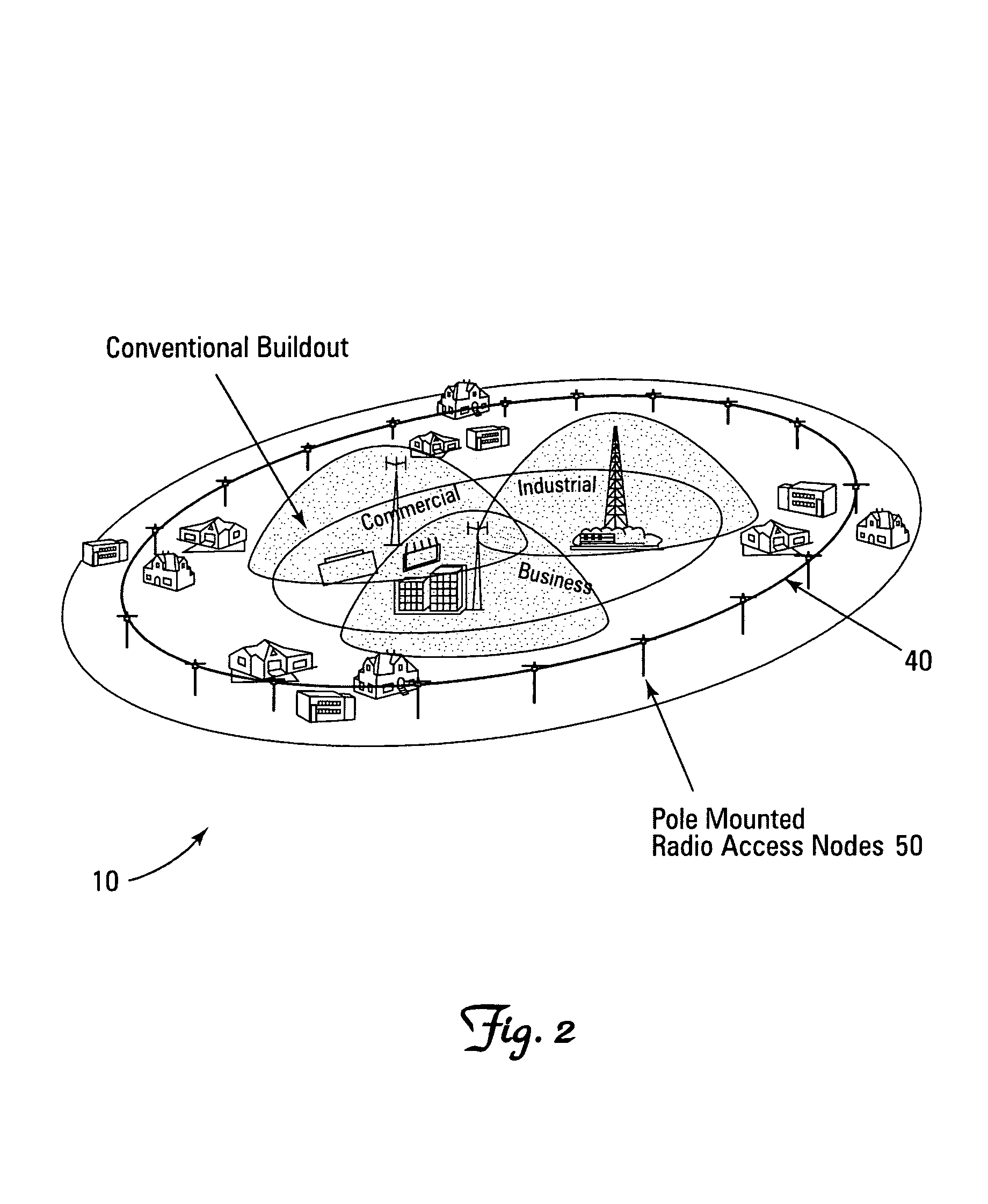
[0009]Certain solutions are emerging that provide an alternative to the tower build out approach. In particular, wireless signal distribution systems employ a distribution media such as a cable television infrastructure or optical fiber data network to distribute Radio Frequency (RF) signals. This allows the capacity of a single base station to be distributed over an area which is the equivalent of multiple traditional cellular sites without degradation in coverage or call quality.
[0011]The present invention is an open access signal distribution system in which a variety of wireless voice, data and other services and applications are supported. The open access system makes use of a distributed Radio Frequency (RF) distribution network and associated network entities that enable the system operator to employ a wireless infrastructure network that may be easily shared among multiple wireless service providers in a given community. The open access system provides the ability for such operators and service providers to share the infrastructure regardless of the specific RF air interface or other signal formatting and / or managing messaging formats that such operators choose to deploy.
[0019]This configuration permits for example, the deployment for the set of shared RANs at common RAN remote locations without having to deploy multiple RAN locations for different air interfaces even when such air interfaces have different receive sensitivities and coverage distances. Thus the Radio Access Nodes for two or more different air interfaces may be co-located throughout the coverage system area reducing the overall system build out requirements.

Problems solved by technology

This is seemingly the best alternative, since Federal laws no longer permit local zoning authorities to completely ban the deployment of wireless infrastructure in a community.
But providing such out of the way locations for towers often does not fully address each and every wireless operator's capacity or coverage need.

Method used


Image

  • Multi-protocol distributed wireless system architecture
  • Multi-protocol distributed wireless system architecture
  • Multi-protocol distributed wireless system architecture

Examples


Embodiment Construction

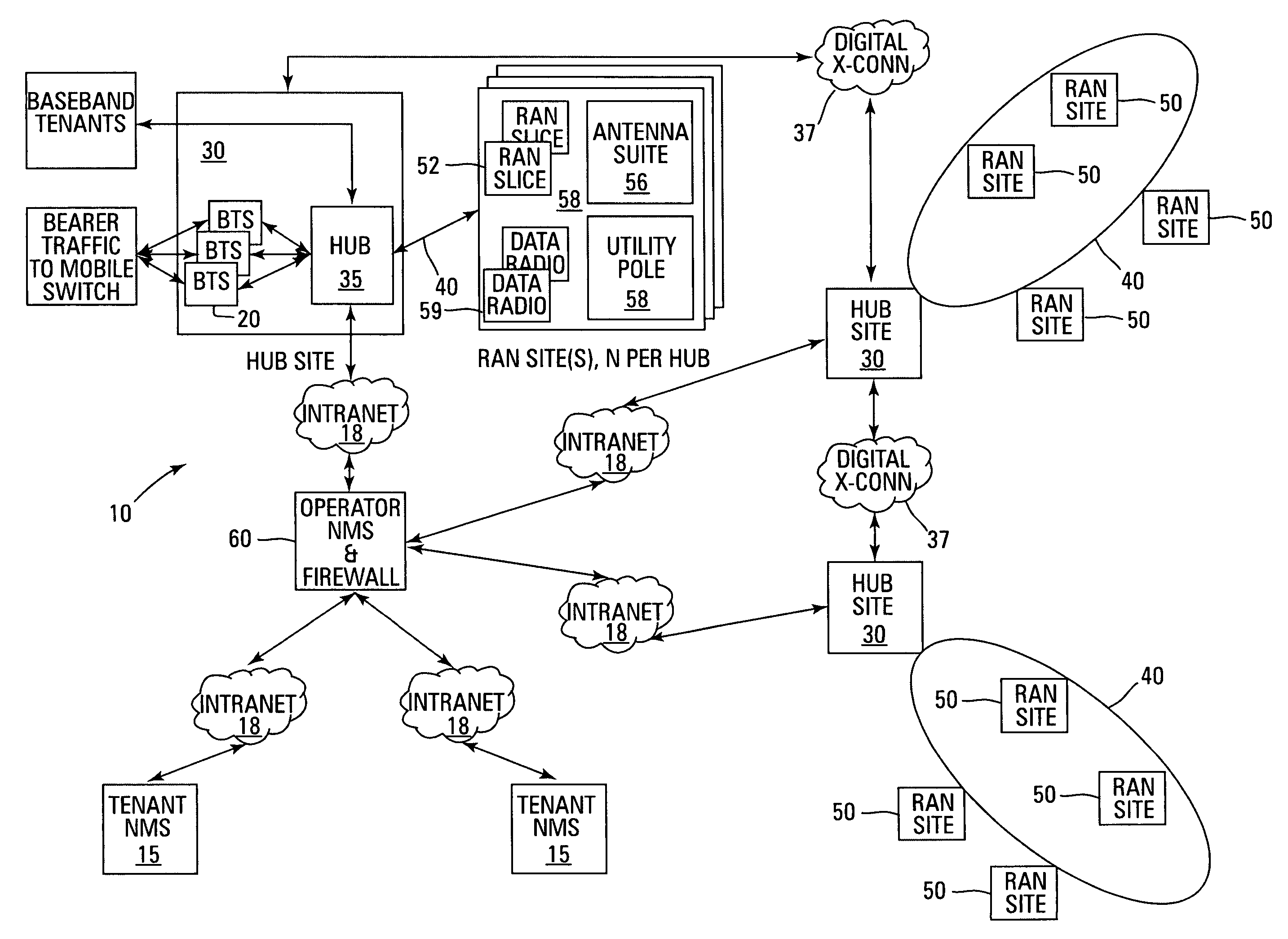
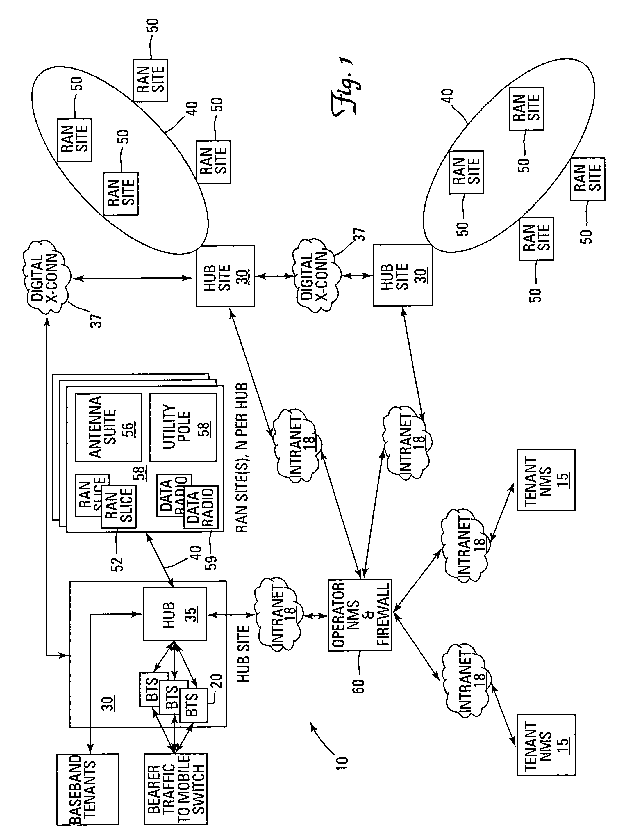
[0031]Turning attention now to the drawings more particularly, FIG. 1 is a diagram of an open access system 10. The open access system 10 is an open access network supporting a multitude of wireless voice, data, video services and applications. Wireless Service Providers (WSP) and Wireless Internet Service (WISP) Providers, commonly known as tenants, may use open access system 10 to either enhance or replace existing networks, wired or wireless, or to develop new networks.

[0032]Open access system 10 is a multi-frequency, multi-protocol Radio Frequency (RF) access network, providing cellular, Personal Communication Services (PCS), and wireless data coverage via a distributed RF access system. Open access system 10 is comprised of base stations 20, located at hub sites 30. The base stations 20 are connected via high speed datalinks 40 to distributed RF access nodes (RANs) 50. The system 10 is, in effect, a signal distribution network and associated management entities that enable a ne...


PUM


Abstract

An open access signal distribution system in which a variety of wireless voice, data and other services and applications are supported. The open access system makes use of a distributed Radio Frequency (RF) distribution network and associated network entities that enable the system operator to employ a wireless infrastructure network that may be easily shared among multiple wireless service providers in a given community. The open access system provides the ability for such operators and service providers to share the infrastructure regardless of the specific RF air interface or other signal formatting and / or managing messaging formats that such operators choose to deploy.

Description

RELATED APPLICATION(S)[0001]This application claims the benefit of U.S. Provisional Application No. 60 / 192,186, filed on Mar. 27, 2000. The entire teachings of the above application(s) are incorporated herein by reference.BACKGROUND OF THE INVENTION[0002]The wireless telecommunication industry continues to experience significant growth and consolidation. In the United States, market penetration is near 32% with approximately 86 million users nationwide. In 1999 the total number of subscribers increased 25% over the previous year, with the average Minutes of Use (MOU) also increasing by about 20% per user. If one considers growth in the digital market, in as short as three years, the digital subscriber base has grown to 49 million users, or approximately equal to the installed number of users of analog legacy systems. Even more interesting is an observation by Verizon Mobile that 70% of their busy hour traffic (an important system design parameter) is digital traffic, although only a...

Claims


Application Information

Patent Timeline
Patent Type & Authority Patents(United States)
IPC IPC(8): H04Q7/30H04W88/10H04W88/14H04W92/02H04W92/04H04W92/12H04W92/14
CPCH04W92/045H04W92/12H04W16/14H04W88/10H04W88/14H04W92/02H04W92/14
Inventor SABAT, JR., JOHNYELLE, PETER
Owner COMMSCOPE TECH LLC
Learn More