
Method and apparatus for providing rate control in a video encoder

a video encoder and rate control technology, applied in the field of video processing, can solve the problem that no prior art scheme provides a robust solution, and achieve the effect of avoiding visible artifacts

Inactive Publication Date: 2005-11-08
ARRIS ENTERPRISES LLC
View PDF18 Cites 135 Cited by
  • Summary
  • Abstract
  • Description
  • Claims
  • Application Information

AI Technical Summary

Benefits of technology

[0012]In accordance with the present invention, rate control is provided in a video encoder having multiple compression engines that process a picture simultaneously and share a common buffer. Nonlinear feedback is used to force a quantizer scale at the last slice of an image panel to be approximately the same as the quantizer scale at the first slice of the image panel. This avoids visible artifacts caused by abrupt changes in the quantizer scale at the panel boundaries.
[0013]A target bit rate for a group of pictures (GOP) is adjusted based on the number of film pictures and non-film pictures currently in the processing pipeline of the compression engines. Since non-film processing in general requires a higher target bit rate, this adjustment allows the rate control algorithm to adapt when the video switches from film to non-film or vice versa.
[0016]The driving step can use, for example, piecewise linear feedback to drive the quantization level of the last slice of each of the image panels toward the target quantization level. The feedback can compensate for variations in the quantization level between the first and last slice of each image panel.

Problems solved by technology

None of the prior art schemes provide a robust solution to the problem of regulating the rate of data production by a plurality of compressors, in order to control the quantization of a digital video encoder that uses parallel compression engines.

Method used


Image

  • Method and apparatus for providing rate control in a video encoder
  • Method and apparatus for providing rate control in a video encoder

Examples


Embodiment Construction

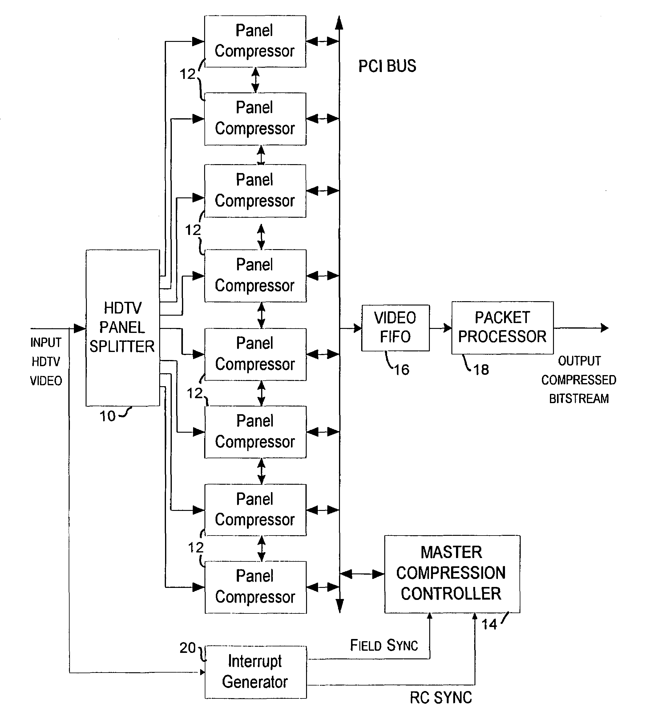
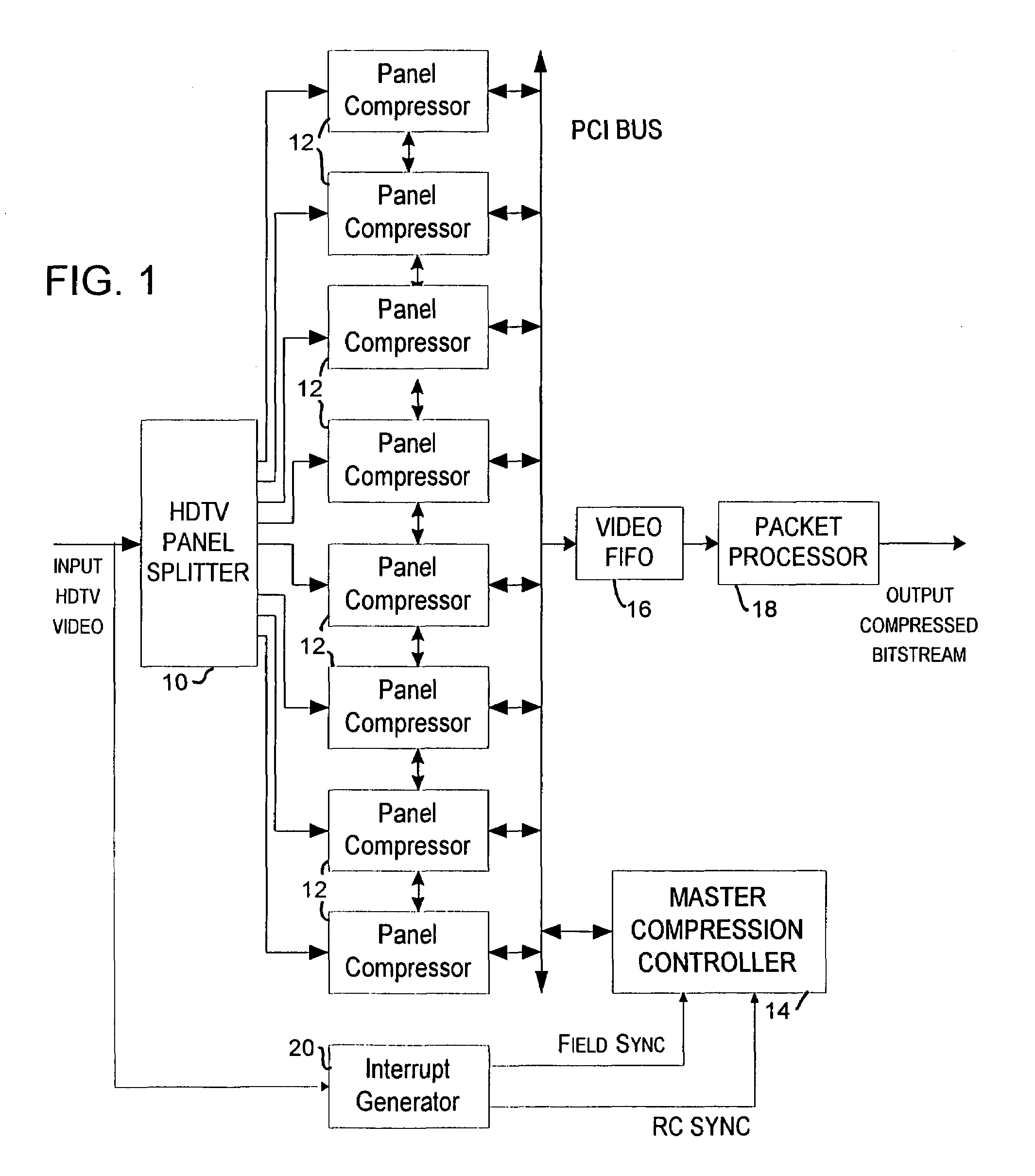
[0026]The present invention provides a method and apparatus for rate control in a digital video encoder that uses multiple compression engines running in parallel. In accordance with a preferred embodiment of the invention as illustrated in FIG. 1, every input picture is partitioned into eight horizontal panels by an HDTV panel splitter 10. Each panel is then compressed by an individual video panel compressor 12, for example, the DvXpert chip available from C-Cube Microsystems of 1778 McCarthy Blvd., Milpitas, Calif. 95035, USA. It should be appreciated that a different number of panels can be utilized, and that the invention can be implemented on video encoders other than the DvXpert encoder described herein.

[0027]The panels into which the input pictures are partitioned are simultaneously compressed during a frame time. The compressed panel data are stored locally on the panel compressor, and then transferred to the primary video FIFO 16 (“video buffer”) within the next frame time....


PUM


Abstract

A method and apparatus are provided for controlling the quantization level in a digital video encoder that comprises a plurality of parallel compression engines (12). The input picture is partitioned into a number of panels (10) and each panel is processed by a distinct compression engine (12). A reference quantizer scale is determined before encoding a frame of video. The reference quantizer scale is used at the first slice of every video image panel being processed by the video encoder. The quantizer scale at the last slice of the image panel is then forced to be the same as the first slice. The forcing step can use a piecewise-linear feedback formula. A group of pictures (GOP) target bit rate is adjusted based on the number of film pictures and non-film pictures currently in the processing pipeline of at least one of the compression engines. A higher target bit rate is provided for non-film pictures. A buffer (16) level of the video encoder is used to control the start of a new group of pictures (GOP). The start of a new GOP is delayed if the buffer (16) does not have sufficient space to accommodate an intra-coded (I) frame for the new GOP.

Description

[0001]This application claims priority from U.S. provisional application No. 60 / 102,800 filed Oct. 2, 1998.BACKGROUND OF THE INVENTION[0002]The present invention relates to video processing, and more particularly to a method and apparatus for controlling the rate of data production by multiple encoding engines provided to compress video in a television encoder, such as a digital high definition television (HDTV) or standard definition television (SDTV) encoder.[0003]The following references are relevant to this disclosure:[0004]1. Advanced Television Systems Committee (ATSC) A53 Standard entitled “ATSC Digital Television Standard.”[0005]2. ATSC A54 Standard entitled “Guide to the use of ATSC Digital Television Standard.”[0006]3. ISO / IEC 13818-2 “Generic Coding of Moving Pictures and Associated Audio: Video” (MPEG2).[0007]4. ISO / IEC JTC1 / SC29 / WG11 / MPEG93 / 457 “MPEG2 Test Model 5.”[0008]5. “Rate Control for the Grand Alliance Prototype Encoder,” Siu-Wai Wu, memo distributed to the Gran...

Claims


Application Information

Patent Timeline
IPC IPC(8): H04B1/66H04N7/12H04N7/26H04N7/50
CPCH04N19/149H04N19/15H04N19/115H04N19/61H04N19/124H04N19/136H04N19/142H04N19/152H04N19/177H04N19/174H04N19/436
Inventor WU, SIU-WAI
Owner ARRIS ENTERPRISES LLC
Learn More