
System for the selective activation of functions in an implantable device by a magnetic field

a magnetic field and function activation technology, applied in the field of implantable medical devices, can solve the problems of prolonging both the effective life and the shelf life of the device, and achieve the effects of less power, less power, and less power

Active Publication Date: 2005-11-08
PACESETTER INC
View PDF9 Cites 110 Cited by
  • Summary
  • Abstract
  • Description
  • Claims
  • Application Information

AI Technical Summary

Benefits of technology

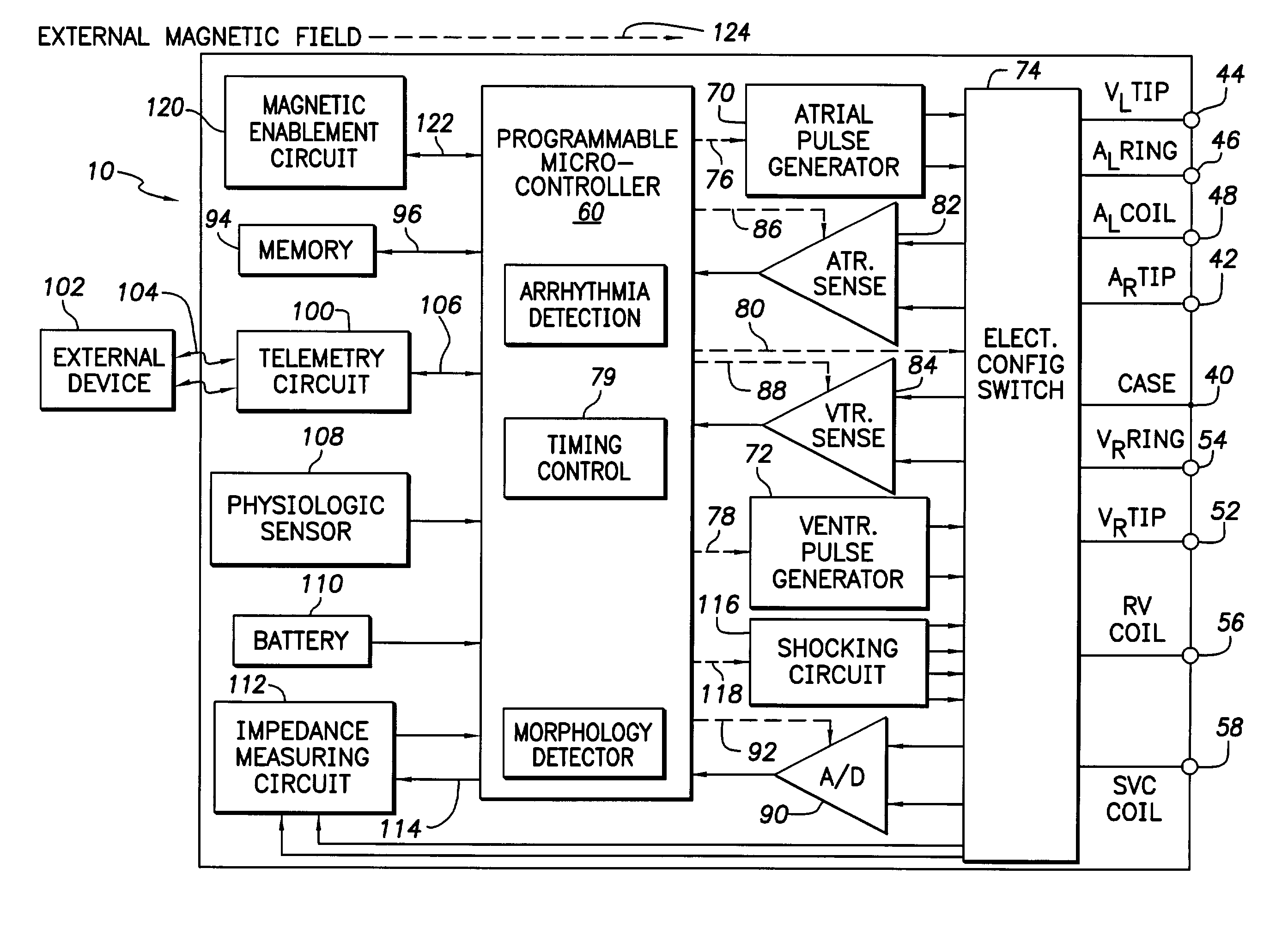
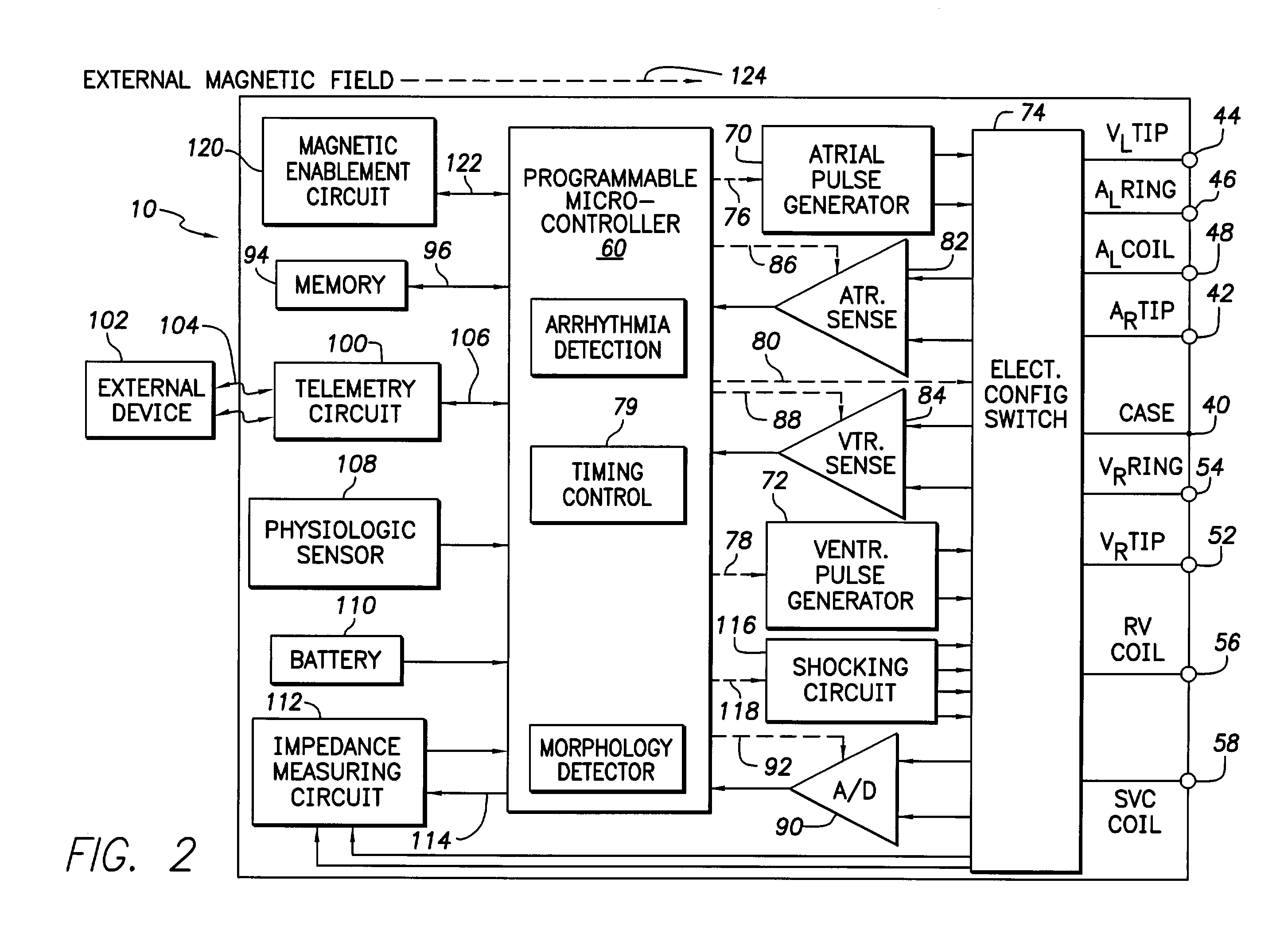
[0012]In another aspect of the invention, the implantable medical device is configured to have a “quiescent” or “low power” state and a dynamic state. In the quiescent state, various amplifiers in the various sensors of the implantable medical device are not powered and the controller is operating in a rest condition where power consumption is reduced. In this particular configuration, the implantable medical device consumes less power than in an active or dynamic state wherein the implantable medical device is powered up for normal activity upon implantation. As a consequence, in the quiescent state, the implantable medical device is consuming less power from the battery, which thereby prolongs both the shelf life of the device and also the effective life of the device after implantation within the patient. In this particular aspect, the implantable medical device can be configured from the “quiescent” or “low power” state to the dynamic state by positioning a magnet, which has a particular selected magnetic field strength. The magnetic field detector provides a signal to the controller indicative of the existence of this magnet, causing the controller to power-up the device into the dynamic state.

Problems solved by technology

As a consequence, in the quiescent state, the implantable medical device is consuming less power from the battery, which thereby prolongs both the shelf life of the device and also the effective life of the device after implantation within the patient.

Method used


Image

  • System for the selective activation of functions in an implantable device by a magnetic field
  • System for the selective activation of functions in an implantable device by a magnetic field
  • System for the selective activation of functions in an implantable device by a magnetic field

Examples


Embodiment Construction

[0022]The following description is of the best mode presently contemplated for practicing the invention. This description is not to be taken in a limiting sense but is made merely for the purpose of describing the general principles of the invention. The scope of the invention should be ascertained with reference to the issued claims. In the description of the invention that follows, like numerals or reference designators will be used to refer to like parts or elements throughout.

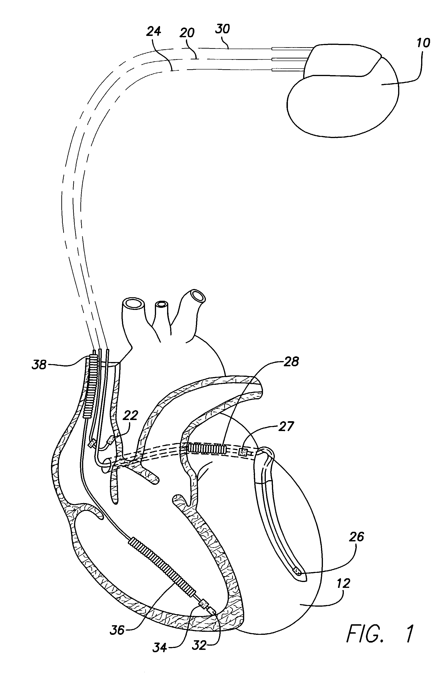
[0023]As shown in FIG. 1, there is a stimulation device 10 in electrical communication with a patient's heart 12 by way of three leads, 20, 24 and 30, suitable for delivering multi-chamber stimulation and shock therapy. To sense atrial cardiac signals and to provide right atrial chamber stimulation therapy, the stimulation device 10 is coupled to an implantable right atrial lead 20 having at least an atrial tip electrode 22, which typically is implanted in the patient's right atrial appendage.

[0024]To sense...


PUM


Abstract

An implantable medical device that includes a magnetic sensor circuit that senses the presence of an external magnetic field and provides a signal that is proportionate to the strength of the magnetic field. The implantable medical device uses the variable signal to determine whether a magnetic field is being applied that is selected to activate a preselected function. In one implementation, the preselected function is a power up sequence.

Description

FIELD OF THE INVENTION[0001]The present invention relates to implantable medical devices and, in particular, concerns an implantable cardiac stimulation device, whereby an induced external magnetic field can be used to activate selected functions of the implanted device.BACKGROUND OF THE INVENTION[0002]Implantable medical devices are being increasingly used to treat medical conditions. These types of devices include pacemakers, implantable cardioverter defibrillators, insulin pumps and the like. Being implanted, these devices are capable of providing therapy directly to the patient on a periodic or continuous basis. These devices are typically battery powered and are susceptible to battery failure over time. One class of commonly used implantable medical devices is implantable cardiac stimulation devices, such as pacemakers and implantable cardioverter defibrillators.[0003]Implantable cardiac stimulation devices are typically implanted within the body cavity of a patient to monitor ...

Claims


Application Information

Patent Timeline
IPC IPC(8): A61N1/362A61N1/37A61N1/372
CPCA61N1/37217
Inventor SHANKAR, BALAKRISHNAN
Owner PACESETTER INC
Learn More