Pipe cleaning and deburring tool

a technology of deburring and pipe cleaning, which is applied in the direction of cleaning machines, manufacturing tools, carpet cleaners, etc., can solve the problems of corrosion of exposed portions of copper and brass pipes and fittings

Inactive Publication Date: 2005-11-15
RED CEDAR PLASTICS
View PDF16 Cites 34 Cited by
  • Summary
  • Abstract
  • Description
  • Claims
  • Application Information

AI Technical Summary

Benefits of technology

[0006]It is a feature of the present invention to provide a single tool which may serve to burnish the exterior or interior of a pipe, and to deburr the end of the pipe.

Problems solved by technology

The exposed portions of copper and brass pipes and fittings are subject to corrosion and contamination which can interfere with the action of surface tension which draws solder or braze alloy into contact when the pipes or fittings are soldered or brazed together.

Method used


Image

  • Pipe cleaning and deburring tool
  • Pipe cleaning and deburring tool
  • Pipe cleaning and deburring tool

Examples


Embodiment Construction

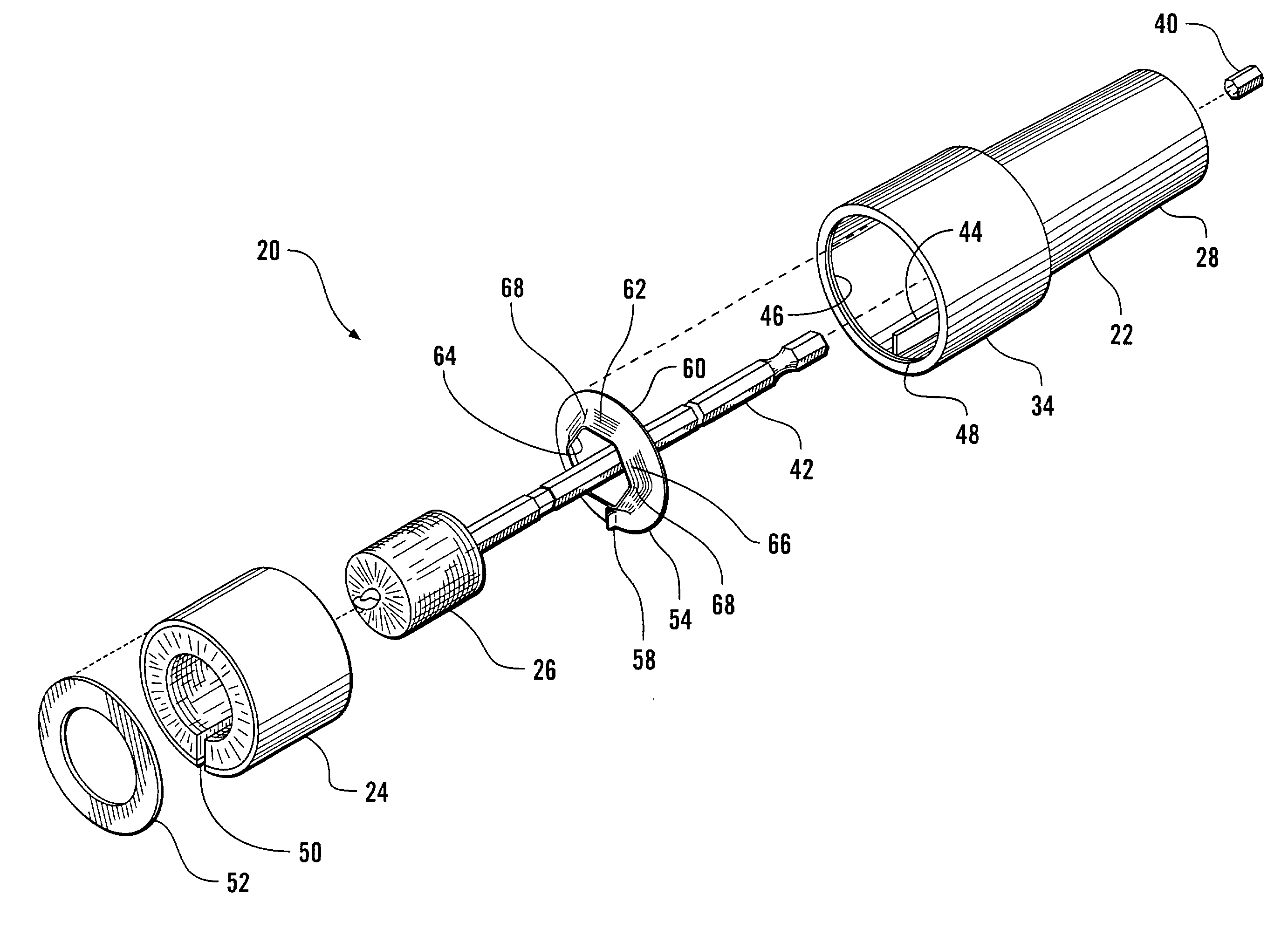
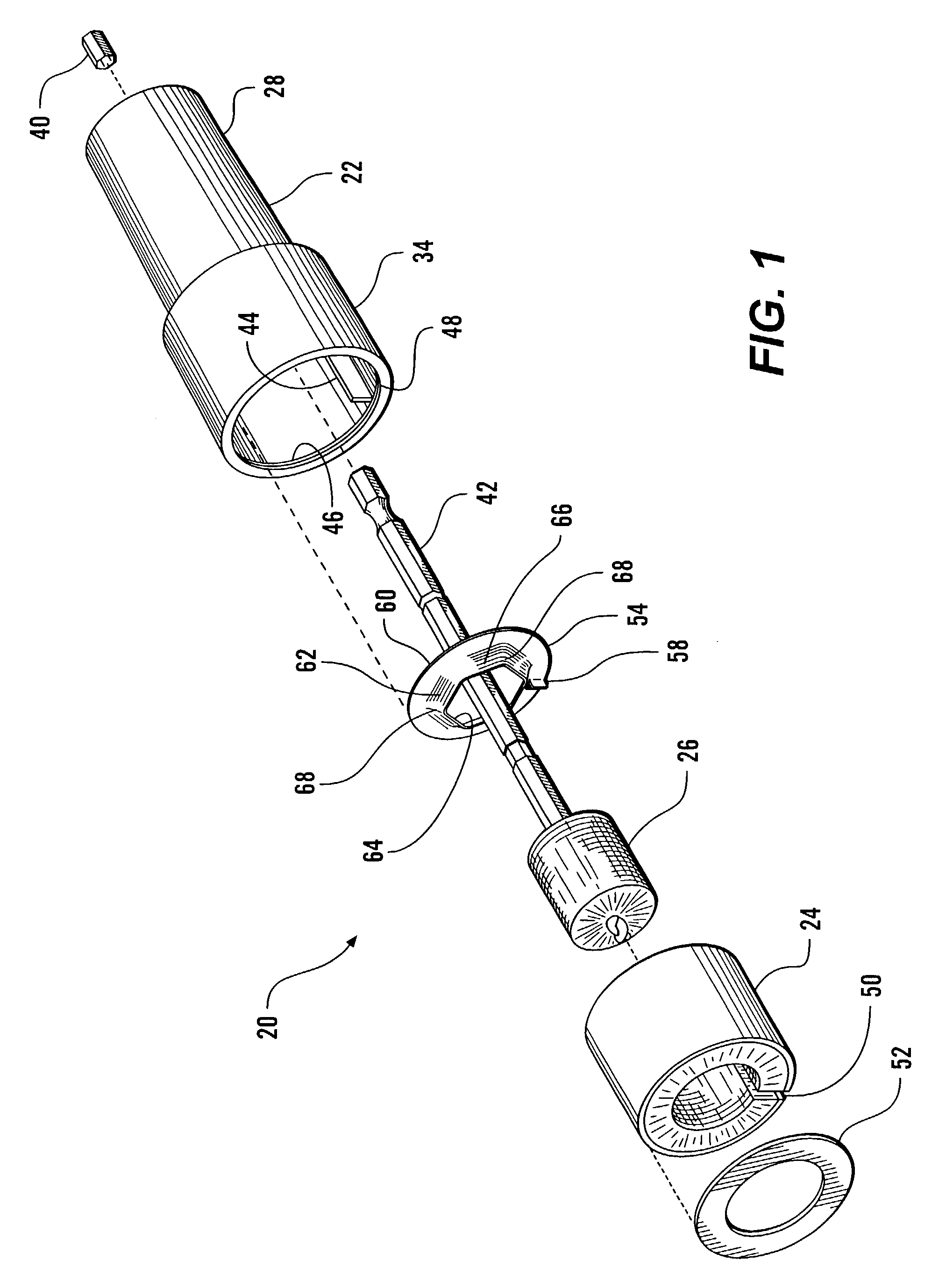
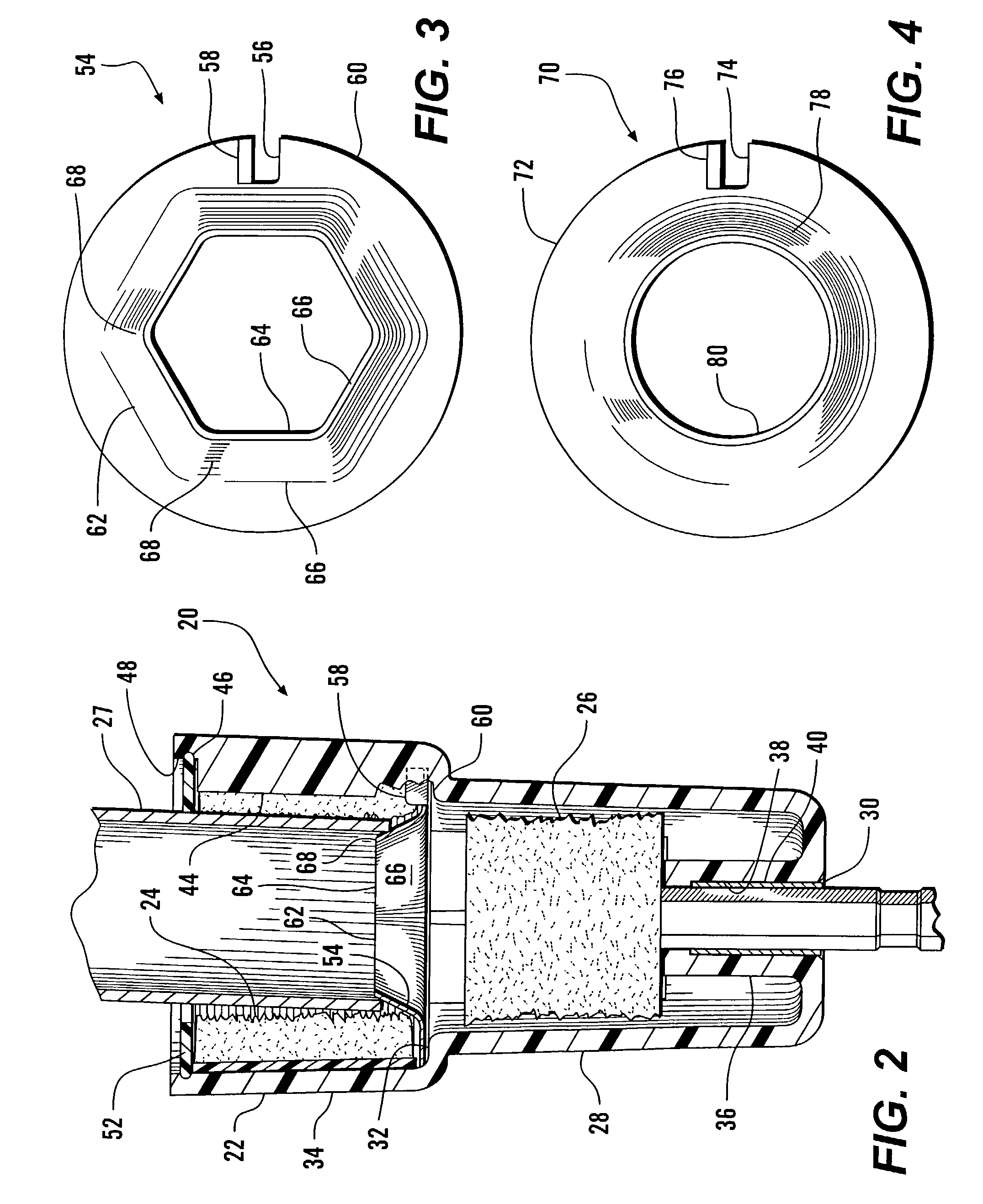
[0014]Referring more particularly to FIGS. 1–4 wherein like numbers refer to similar parts, a pipe burnishing and deburring tool 20 is shown in FIG. 1 and FIG. 2. The tool 20 has a housing 22, preferably formed of molded plastic material, for example polycarbonate. As shown in FIG. 1, an exterior wire brush 24 and an interior wire brush 26 are mounted within the housing 22 for the burnishing of the exterior or interior of a pipe segment 27 respectively.

[0015]The housing 22, as best shown in FIG. 2, has a rear shell 28 which extends frontwardly from a rear opening 30 to a radially outwardly protruding radial flange 32 which adjoins a frontwardly extending front shell 34 which is coaxial with the rear shell and of greater diameter. A shaft tube 36 extends frontwardly from the rear opening 30 and defines a non-round shaft passage 38 which receives a roughly hexagonal metal bushing 40. The interior brush 26 has a rearwardly extending non-round shaft 42 which is keyed to the shaft tube t...


PUM

PropertyMeasurementUnit
angleaaaaaaaaaa
angleaaaaaaaaaa
thickaaaaaaaaaa

Abstract

A plastic housing has a front shell with inwardly protruding bristles of an exterior wire brush, and a rear shell which retractably receives the outwardly protruding bristles of an interior wire brush. The interior brush is mounted to a shaft which engages the housing, and which is driven by a motor, such as by a power drill. A ring-like deburring element is mounted to the shell between the front shell and the rear shell, and has an inwardly and frontwardly protruding generally frustoconical first wall forming a deburring element which defines a central opening through which the interior brush may be projected and retracted. The first wall may be planar segments, or may have a circular cross section. The deburring element serves to position a pipe for burnishing by the exterior brush, and also deburrs the end of the inserted pipe.

Description

CROSS REFERENCES TO RELATED APPLICATIONS[0001]Not applicable.STATEMENT AS TO RIGHTS TO INVENTIONS MADE UNDER FEDERALLY SPONSORED RESEARCH AND DEVELOPMENT[0002]Not applicable.BACKGROUND OF THE INVENTION[0003]The present invention relates to apparatus for treating the cut ends of pipes and fittings.[0004]The exposed portions of copper and brass pipes and fittings are subject to corrosion and contamination which can interfere with the action of surface tension which draws solder or braze alloy into contact when the pipes or fittings are soldered or brazed together. Thus it is required to clean the pipe surfaces which are to be joined. Moreover, in some applications it is required to remove the projecting burrs of copper or brass before joining the pipes. Although many tools are available to perform the burnishing of a pipe interior or exterior, or to deburr a pipe, convenience and ready availability of all necessary tools can speed along the process of preparing multiple pipe surfaces....

Claims


Application Information

Patent Timeline
Patent Type & Authority Patents(United States)
IPC IPC(8): B08B9/02B23B5/16B23D79/02
CPCB08B9/021B08B9/023B23B5/167B23D79/02
Inventor KADINGER, KELLY K.SCHONEBAUM, THEODORE
Owner RED CEDAR PLASTICS
Why Eureka
Try Eureka